The Swiss lever escapement – Part 1: For everyone
Part 2 · Workshop will appear next week, on 04 November 2026.
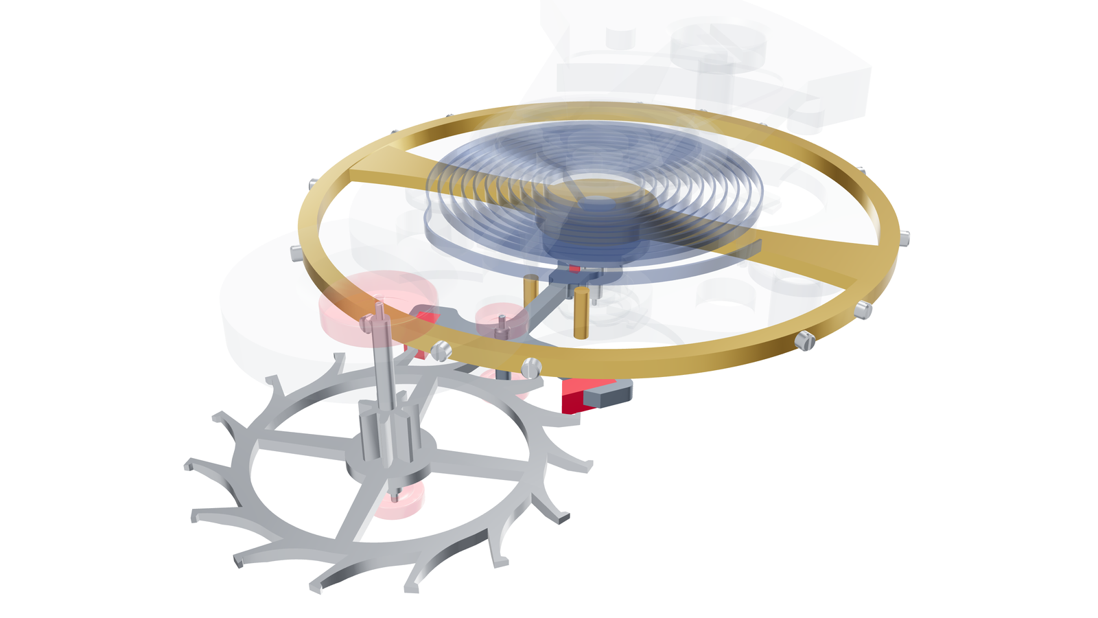
The escapement is one of the smallest assemblies in a watch movement, yet it determines whether the watch runs, how steadily it keeps time and how much energy reaches the balance. At 18,000 half-oscillations per hour, a tooth of the escape wheel drops onto one of the two pallets, the small ruby stones on the pallet fork, 432,000 times a day; at 28,800, it happens 691,200 times, or around 158 and 252 million times a year respectively.
Hundredths of a millimetre at two ruby pallets determine how the watch runs. But how do the parts interact, and what does a watchmaker need to know to recognise faults quickly and avoid adjusting things at random? In this article, we start with the principles and work through the operation, components, relationships, faults and adjustments step by step.
Learning exercise: As originally constructed, the model shown had 1.22° of run to the banking on the entry side, but only 0.34° on the exit side: the small remaining distance the lever travels along the pallet's locking face after a tooth drops, until it reaches its stop. Which pallet needs adjusting, in which direction, by how much, and what must be checked afterwards? The answer follows in Part 2; the full solution is under The learning exercise solved.

The article has four parts, arranged by depth; each topic has a main location with an anchor that the other passages link to.
| Who | Reading route |
|---|---|
| Anyone who wants to know how a watch ticks | Part 1 and the history, around 25 minutes in total |
| Watchmakers at the bench | Part 2, or go straight to: From findings to diagnosis, Checks at the bench, Escapement faults |
| Students preparing for the master watchmaker examination | Part 2 and Part 3, with the questions at the end of each part and the learning exercise |
| Designers | Part 4, with links to the fundamentals |
Contents
- Part 1 · For everyone: How the Swiss lever escapement works
- Part 2 · At the bench: Naming the escapement's parts precisely · Measure first: the escapement on the timing machine · Checks at the bench · Moving pallets and adjusting the banking · Escapement faults: from symptom to cause · Lubrication and final checks
- Part 3 · Master level: A closer look: terms, angles, draw and safety features · Pallet adjustment in numbers · Timing machines and lift angle in formulae · Escapement and timekeeping · Origins and related escapements
- Part 4 · For designers: Designing the Swiss lever escapement · Energy and efficiency
- Appendix: Reference material, terms, questions and sources
The model: All images and animations come from one 3D model: an escape wheel with 15 teeth, 18,000 half-oscillations per hour, adjusted according to the workshop rule in Part 2. The sequences are determined from the visible contacts and run in slow motion without inertia, meaning without the momentum of the moving parts: high-speed recordings of real escapements show rebounds and dynamic effects that the idealised animation does not show. The model's values are listed at the start of Part 2 and in the appendix. Rotate the whole model
Part 1 · For everyone
How the Swiss lever escapement works
In the first part, we start from scratch and introduce the movements, components and first technical terms. Where does the energy come from that keeps a watch ticking, and how is that energy passed on? What makes the ticking sound? How precisely must everything fit for the escapement to work, and how much energy finally reaches the balance?
Part 2 returns to the same subjects with the precise names, figures and practical workshop procedures.
Why a watch needs an escapement
A mechanical watch has two assemblies that need each other. The mainspring, the coiled steel spring inside the barrel, supplies the force. Through the going train, the chain of gears that also drives the hands, this force reaches the final wheel, the escape wheel, known in German as Ankerrad, Hemmrad or Hemmungsrad. The balance and its hairspring, a small flywheel with a spring as fine as a hair*, meanwhile swing back and forth at a steady rhythm. Between them sits the escapement.
*Every watchmaker knows the story: unfortunately, customers occasionally come into the workshop having tried to pull this supposed “hair” out of the movement because they thought it was the cause of the fault. The damage is usually immense.
The mainspring supplies the watch's driving energy, while the balance provides the steady rhythm that divides the day into equal pieces. Between them lies the escapement. Remove this assembly and the going train runs down rapidly without restraint: the hands race, and the energy intended to last a day or more is used up in a minute. Remove the driving force instead, and the balance's swing gets smaller each time because every oscillation loses some energy through friction, and it soon stops. Watchmakers actually carry out the first experiment deliberately at the bench: if the going train runs down freely without the pallet fork and the escape wheel briefly swings back at the end, the train is free (Functional checks). (This is of course tested without the hands fitted and with the mainspring only lightly wound.)

The escapement connects the two and performs two tasks. It locks the going train and releases it only in time with the balance, tooth by tooth. And it gives the balance a small push in every half-oscillation to replace the energy the balance continually loses through friction and shocks.
Pushing a child on a swing is a good analogy for this push. In the same way, the lever pushes the balance at its central position. The swing moves freely, reverses direction and comes back. Its length determines its rhythm; the hand only replaces the energy lost through air friction. In the balance, this push comes around the rest position, where it is moving fastest. The difference from a swing, however, is that the lever pushes the balance on both the forward and the return swing.
For the going train, think of a turnstile at a swimming-pool entrance that lets exactly one person through with every step. For each half-oscillation of the balance, the escape wheel is allowed to advance by half a tooth pitch, half the distance from one tooth to the next. After two half-oscillations, it has advanced by exactly one tooth, and the hands move a tiny step with every tick.
But in this analogy the balance is not merely pushed: shortly before receiving the push, it first releases the very mechanism that pushes it. It releases the gears, which move a tiny distance and immediately supply the push, passed through the escape-wheel teeth to the large red rubies (pallets), and from these pallets through the pivoting lever and the small ruby impulse pin back to the balance — an ingenious invention — because as long as driving force is applied to the escape wheel, the watch keeps running!
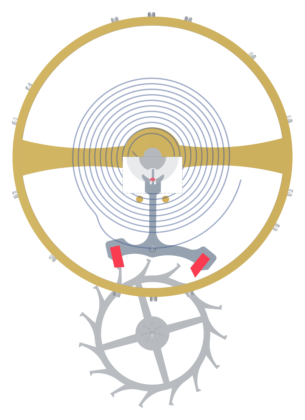
Key point: The escapement counts and pushes. It lets the going train advance only in time with the balance, and returns the lost energy to the balance in every half-oscillation.
Oscillation and amplitude: how watchmakers count
We need three new terms for the balance's motion. The dead point is the rest position, the position in which the hairspring is relaxed and the small ruby pin points directly towards the escape wheel. A half-oscillation travels from one turning point through the dead point to the other turning point (Theorie der Uhrmacherei, WOSTEP Feinregulierung). That is one tick. An oscillation is the journey out and back: tick and tock. In the workshop, watchmakers often speak of half-oscillations, or beats (also called vibrations), because these are traditionally counted per hour, abbreviated A/h in German, after the French word alternance for a half-oscillation. Counting half-oscillations became established in watchmaking because simply counting the watch's ticks already counts its half-oscillations.
18,000 A/h means 5 half-oscillations per second, or 2.5 full oscillations, or 2.5 hertz (Hz). 28,800 A/h means 8 half-oscillations per second, or 4 Hz.
Amplitude is the balance's greatest angular displacement; in watchmaking, it refers to one side, from the dead point to the turning point. When a watchmaker speaks of 180° amplitude, this means that a point on the balance rim swings 180° to the right and 180° to the left. It therefore travels 360° per half-oscillation and 720° per oscillation. At 270° amplitude, it travels 540° per half-oscillation. Weger drew amplitude this way as early as 1967 in the Neue Uhrmacher-Zeitung: as an arc from the centreline to the turning point.

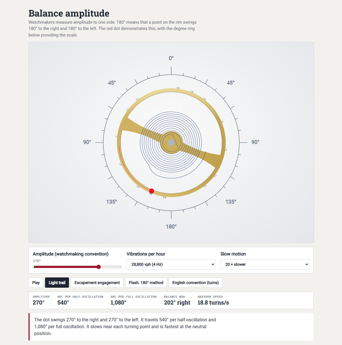
A modern wristwatch, lying flat and fully wound, usually has an amplitude of 260 to 310°; in a vertical position it is around 20 to 60° lower, depending on the movement. More on amplitude under What the timing machine measures and which values apply.
But take care: not every source counts this way. Older English and American books give amplitude in “turns”, meaning the whole arc from turning point to turning point; one turn corresponds to 180° amplitude, so 1½ turns means 270°. Likewise, “1¾ Umgang” in older German books or a “swing arc of 540°” refer to the whole arc. Occasionally, you also read that an oscillation consists of two amplitudes. This confuses an angle with a process: an oscillation consists of two half-oscillations, and each half-oscillation covers twice the amplitude.
The balance moves like a wild swing that many a child would enjoy. It is fastest at the dead point and stops for a tiny instant at each turning point. The balance of a wristwatch running at 4 Hz and 280° amplitude rotates at just under 20 revolutions per second.
The escapement engages only near the dead point. The arc of the balance's motion during which it is connected to the lever is called the lift angle. It usually lies between 30 and a little over 50°, and is around 35° in our model. Values for individual calibres and the ranges found in workshop practice and the literature are also listed under timing-machine values.
This engagement is brief. In our model, running at 18,000 A/h and 280° amplitude, it lasts around 8 of the 200 milliseconds (thousandths of a second) in a half-oscillation, or around 4%. In a 4 Hz wristwatch with a 52° lift angle and the same amplitude, it lasts around 7.4 of 125 milliseconds, just under 6%. For the whole remainder of the half-oscillation, the balance runs freely. This part is called the supplementary arc: the arc that, added to the lift angle, completes the full arc of the half-oscillation.

One amplitude is particularly useful at the bench: at exactly 180°, both turning points lie at the same place, opposite the rest position. A marked point on the rim then flashes at exactly the same location on both the left and right swings; the amplitude animation shows this in “Blitz” (flash) mode. This is the basis of the 180° method I use to determine a movement's lift angle.
Key point: Watchmakers count amplitude on one side. 270° means 270° from the zero position to the turning point, making 540° per half-oscillation in total.
The components at a glance
The Swiss lever escapement consists of only a few parts, and each has a clear task.
The escape wheel sits at the end of the going train. Its teeth are club teeth, with a broad, sloping face rather than a point; the model shown has 15 teeth, as do almost all pocket watches. The pallet fork, or lever, is a small lever pivoted on a staff. At the front it carries two ruby pallets (now synthetic), which engage the escape wheel alternately: the entry pallet, where the teeth enter the region of the lever, and the exit pallet, where they leave it. At the rear it ends in the fork, whose two tips are called horns, or sometimes prongs.
The double roller sits on the balance staff: two discs, one above the other. The larger upper roller carries the impulse pin (roller jewel), a small ruby pin that engages the fork; today it usually has a semicircular cross-section; when the balance is in its central, or zero, position, its flat side faces the pallet staff. The smaller disc is called the safety roller and has a cut-out, or passing hollow. Two banking pins, which act as stops, limit the lever's travel in either direction; in many modern movements, fixed stops in the mainplate perform this task.
That leaves a short pin on the fork, facing the edge of the safety roller, which can pass through the hollow only when the balance is near its zero position. This component is called the guard pin (German names include Sicherheitsmesser, Sicherheitsstift, Lanze, Dard, Sicherheitsfinger and others). In the German version of this article, we use Sicherheitsmesser or Messer; here we use guard pin.
The guard pin's many names
| Language | Names |
|---|---|
| German | Sicherheitsmesser, Sicherheitsstift, Sicherungsmesser, Sicherungsstift, Ankermesser, Messer, Lanze, Dard, Sicherheitsfinger |
| English | guard pin, dart, safety pin |
| French | dard; historically coin or goupille de sécurité |
| German, historical | Sicherungsgabel (the complete guard-pin and fork assembly) |

The lever is therefore like a seesaw with two fingers that alternately engage the escape wheel. The fork is the coupling into which the impulse pin engages each time it passes through the dead point. The banking pins are stops for the lever's tail, like doorstops on the floor. The guard pin acts like a door chain intended to hold a door open: it allows the lever to move only a small distance away from the doorstop while the balance is out in the supplementary arc (because the lever can cross to the other side only when the hollow is opposite the guard pin).
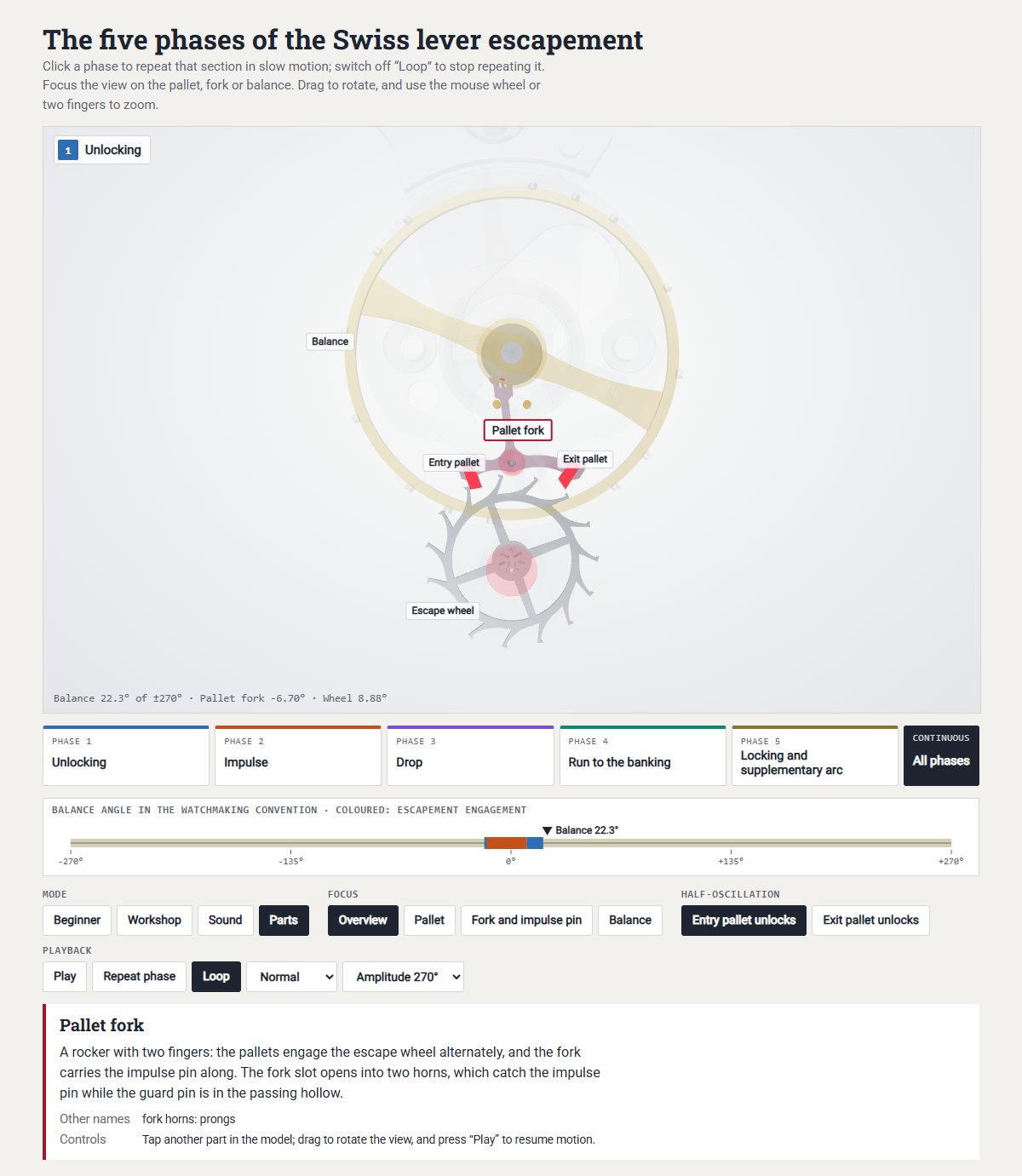
You can rotate the entire model freely and view it from all sides. The next section names the pallet and tooth faces where they do their work; the precise names and details of all faces and edges follow in Part 2 under Faces and edges.
One tick in five phases
The easiest way to understand the escapement is to watch it. The animation shows one half-oscillation divided into its five textbook phases.
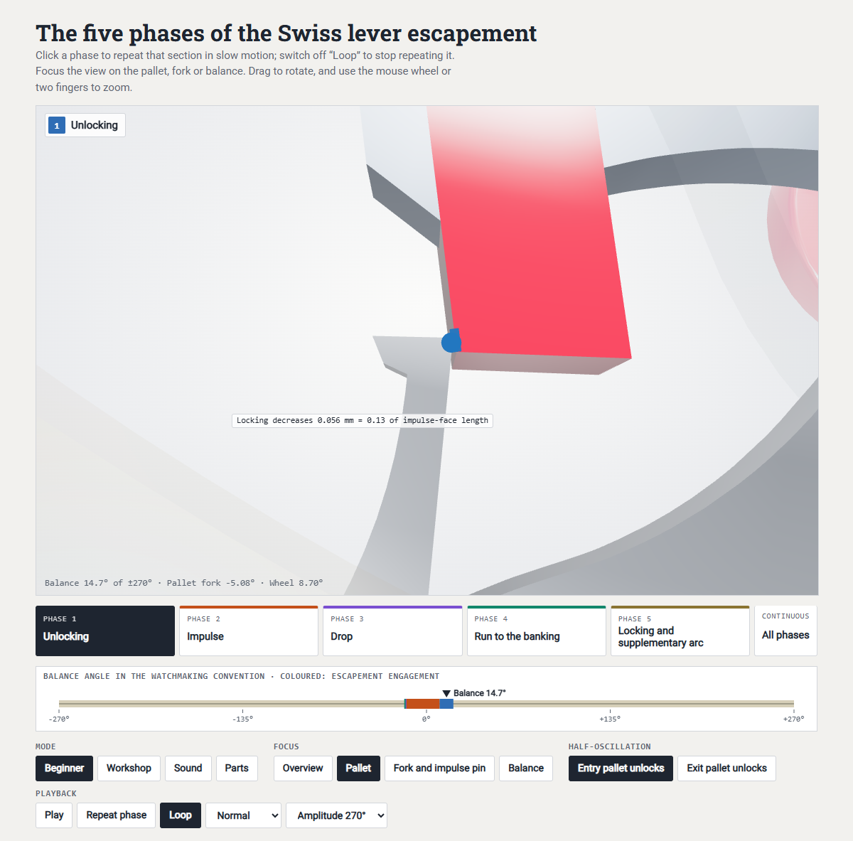
Clicking a phase plays it in slow motion on a loop; “Schleife” (loop) turns repetition off, and “Phase wiederholen” (repeat phase) restarts it; the Palette, Gabel and Unruh buttons centre the pallet, fork or balance respectively. All animations in this article load only when clicked; until then, a still image is shown; each check and fault described later opens the animation directly at the relevant phase.

Because the animations run in slow motion without inertia, the sequence looks calmer than it really is. In reality, things are more lively: in high-speed recordings, a tooth bounces on the pallet roughly twice after the drop, like a dropped ball, before settling; how often and how strongly it bounces depends on shape, force and cleanliness (The dynamics behind the slow motion). The lever's impact against the banking pins can look similar, which is why the thickness, position and shape of the banking pins matter more to good timekeeping than one might think. Nowadays, escapements are developed through dynamic simulation and intensive testing until these sources of disturbance are reduced as far as possible. A watch on the wrist, under constant jolts, never runs as smoothly as this idealised presentation suggests.
The starting image: at rest with the mainspring run down. When the watch has stopped with its mainspring run down, the hairspring holds the balance at the dead point. The escape-wheel staff, pallet staff, guard pin, impulse pin and balance staff then lie on one line, and a tooth is about halfway across a pallet's impulse face, its sloping end face. When force is applied to the spring, this tooth presses against the slope and pushes the lever sideways, and the fork pushes the impulse pin. The first impulse begins by itself and the watch starts.

Good to know: this is why a well-adjusted lever watch often starts by itself when wound. If it needs shaking first, its beat may be incorrectly set, meaning the balance's position relative to the lever: at the dead point, the impulse pin then does not lie exactly on the line between balance and lever. Or the going train lacks power.
The starting position while running. The balance returns from its supplementary arc towards the dead point. The lever rests against one banking pin, and a tooth presses on the locking face of the entry pallet, the face on which it rests while locked. The escape wheel is stationary although the spring drives it, because the pallet locks it like a bolt. At the same time, the tooth's pressure on the pallet holds the lever securely against the banking.
Phase 1: unlocking. Shortly before the dead point, the impulse pin meets the fork and turns the lever away from the banking pin. This withdraws the pallet a little from the escape wheel: it draws the bolt back. The tooth slides over the locking face to the locking corner, the edge where locking and impulse faces meet. Because the locking face is inclined, it even pushes the escape wheel back slightly as it moves. The balance pays for the work of unlocking from its own oscillating energy; in the model it turns through around 10° during unlocking. Phase 1 in the animation
What matters here: how deeply the tooth locks and how strongly the slope draws, namely locking depth and draw. This is why locking depth and draw should not be set unnecessarily large, because a great deal of oscillating energy is lost here. The simplest way to reduce the balance's amplitude is to increase the locking depth by opening the lever's banking slightly.
Phase 2: impulse. As soon as the heel of the tooth, the edge at its locking face, has passed the locking corner, it is on the impulse face. Now the mainspring does the work: the escape-wheel tooth presses against the sloping impulse face, and the pallet moves sideways as if pushed by a wedge. First the heel slides over the pallet's impulse face; then the pallet corner slides over the club tooth's sloping end, its own small impulse face. The lever keeps turning and the fork gives the impulse pin the push that we will from now on call by its correct technical name, impulse. During impulse the balance passes through the dead point; in the model, impulse takes around 24° of its travel. Phase 2 in the animation
What matters here: how much energy reaches the balance; fork clearance also plays a part.
Phase 3: drop. At the end of impulse, the pallet corner leaves the tooth's impulse face, and the tooth is released and drops. For a moment, nothing restrains the escape wheel, and it turns until another tooth drops onto the second pallet's locking face. This jump is called the drop; in the model, it is around 2° at the escape wheel. The point where the tooth first lands is called the initial locking point, and its depth on the locking face, measured from the pallet's edge, is the initial locking. This impact is the most distinct sound in the tick. Phase 3 in the animation
Here lies an important relationship for understanding escapement adjustment: where impulse ends on one pallet determines where the tooth lands on the other. Everything discussed later about moving the pallets builds on this (The core rule of pallet adjustment).
What matters here: initial locking and drop; in the worst case, the tooth lands directly on the impulse face: see Drop and Tooth on the impulse face.
Phase 4: run to the banking. At the instant of drop, the lever has not yet reached the banking pin. To draw the lever securely to the banking and hold it there so that it does not disturb the balance's oscillation, the locking face is slightly inclined. This inclination of the locking face produces what is called draw: the tooth presses on this inclined plane and draws the pallet towards the escape wheel (like the component of gravity acting down a slope) until the lever's tail rests against the banking pin. The tooth slides along the inclined plane from the point of initial locking to the locking depth, the depth at which it finally rests on the pallet. The short distance through which the lever turns from the drop to the banking pin is called the run to the banking. It is a reserve: even if the escape wheel is not perfectly round, one tooth is a little longer, or the pivots have play, the previous tooth reliably clears the impulse face before the lever reaches the banking pin. Without this reserve, the slightest irregularity would immediately lock up the escapement. Phase 4 in the animation
What matters here: the run to the banking, exactly the quantity that was unequal in our model before adjustment: see Learning exercise.
Phase 5: locking and supplementary arc. The escape wheel is now stationary again, the lever rests securely against the banking pin, and the impulse pin leaves the fork. The guard pin faces the outer surface of the safety roller with a small clearance. The balance swings freely out to its turning point and returns without anything touching it: this is the supplementary arc. It also defines the detached escapement, because the balance (oscillator) can complete its supplementary arc entirely freely, without contact with the escapement. The half-oscillation ends at the turning point, and the return journey already belongs to the next one. Shortly before the dead point, everything starts again, mirrored at the other pallet. Two half-oscillations thus advance the escape wheel by exactly one tooth. Phase 5 in the animation
How the guard pin and horns hold the lever during a shock: see Safety features, Guard-pin clearance and Horn clearance.

The main sounds in the tick are the drop and the lever's impact against the banking pin, which occur almost together; the quieter unlocking and impulse precede them. More detail is given under What you hear; the chapter Measure first explains how a timing machine evaluates these sounds.
Key point: Unlocking, impulse, drop, run to the banking, locking: these five phases occur in every half-oscillation, twice per oscillation, and eight times per second at 28,800 A/h.
Bolts, reserves and safety features
The pallet on whose locking face the tooth rests is like a bolt locking the going train, and it must engage deeply enough. If the tooth sits too close to the edge, even a light shock can move the lever far enough for the tooth to slip from the locking face onto the impulse face; the escape wheel then drives the lever at the wrong moment, and the lever can disturb the balance's oscillation. If it sits too deep, the balance has to withdraw the bolt further against the slope at each unlocking, costing energy with every tick. This is why the pallets can be moved in the lever and are adjusted to hundredths of a millimetre.

To keep the bolt secure during shocks or vibration, the locking face is inclined. Its slope is arranged so that the tooth's pressure draws the pallet into the escape wheel and presses the lever against the banking pin. This is the draw from Phase 4. If something knocks the lever away from the banking pin, draw immediately brings it back.
But what holds the lever during the supplementary arc, when the balance is far out and no impulse pin sits between the horns? Two safety features take over from each other. While the balance is far away, the guard pin faces the edge of the safety roller and allows the lever to move only a short distance from the banking pin, too little for the tooth to leave the locking face. Near the dead point, the guard pin must pass through the hollow; here the horns take over, bracing against the impulse pin.
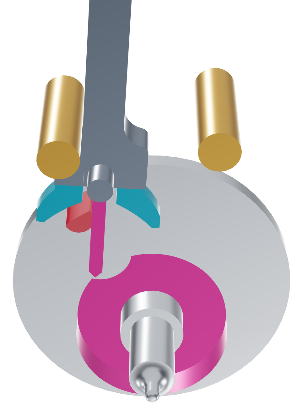
Small clearances remain between guard pin and roller, between horns and impulse pin, and between impulse pin and fork. In engineering, a small gap between components that permits freedom of movement is called “play” or “clearance”. In watchmaking, these are called guard-pin clearance, horn clearance and fork clearance. They are the reserves. Without them, the guard pin would rub against the roller and slow the balance. If guard-pin or horn clearance is too large, a shock can move the lever far enough for the tooth to reach the impulse face after all; excessive fork clearance costs energy and reduces the escapement's efficiency. These clearances are checked under magnification with the movement stopped (Checks at the bench); with the movement running, the timing machine can give indications of whether the escapement is working correctly overall.
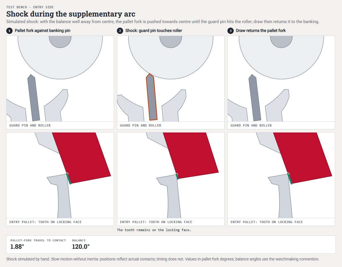
This already gives us a sense of the solution to the introductory learning exercise: the pallet's depth determines where the tooth lands, with an interaction on both sides. The banking pin determines how far the lever continues after the drop. Two checks on each side, where the tooth lands and how far the lever travels afterwards, are therefore enough to tell precisely whether a pallet must be moved or the spacing of the banking pins changed.
(In modern wristwatches, the lever banking is often fixed and integrated into the pallet bridge; in that case the run to the banking cannot be adjusted, and corrections can only be made through the pallet depth. If there is absolutely no alternative and a replacement part is unavailable, a very careful correction of the banking by staking or filing can save the watch, provided one is capable of carrying out this work with the utmost precision.)
In Part 1, we say “set deeper” when a pallet is moved so that the tooth rests deeper on it, and “set shallower” in the opposite case; the German workshop terms heraus and hinein (“out” and “in”) are explained in Out means deeper. How to use this rule to solve the learning exercise precisely is shown in The learning exercise solved.
Our model shows how narrow the window is. Set both pallets only a few hundredths of a millimetre shallower than the correct adjustment and the tooth drops directly onto the impulse face rather than the locking face; set them too deep and the escapement locks up. From the correct setting, the model has just under 0.025 mm towards the shallow limit and 0.045 mm towards the deep limit, a total of just under 0.07 mm, about the thickness of a hair. Both extremes are shown under Limiting cases.
Key point: Every clearance is a reserve, large enough for shocks and tolerances, small enough to avoid wasting energy.
During training, we adjusted numerous escapements. I was tempted to set my own watch's clearances and tolerances as finely as possible, because it is easy to think “the finer, the higher the quality”. No sooner said than done, but a short time later my watch stopped on my wrist. While removing the movement for diagnosis, I loosened a movement retaining screw, and the movement immediately started running again: a very slight strain, which would normally have had no effect, had bent the movement by a minute amount and turned a very small clearance into a bind.
---
It is not advisable to set a watch's clearances and tolerances as small as possible, because the reserve is there for a reason. Temperature changes, shocks, strain and dirt can quickly cause problems when settings are too tight, even though they would normally have no effect on the watch at all.
Detached, robust, widespread: classification
Watchmakers classify escapements according to what happens to the balance during the supplementary arc. In recoil escapements such as the verge escapement, the escape wheel remains in contact with the oscillator and is turned backwards during the supplementary arc. In frictional-rest escapements such as the cylinder escapement or the Graham deadbeat escapement, the tooth rests on the oscillator or on a part rigidly attached to it, rubbing against it. In detached escapements, nothing touches the balance during the supplementary arc; these include the Swiss lever escapement, the pin-pallet escapement, the chronometer escapement and the co-axial escapement (and many other, less well-known escapements).
For a balance and hairspring this is a major advantage, because recoil and frictional escapements disturb their steady rate considerably. In a detached escapement, the balance swings through most of its travel with its hairspring alone, without any connection to the escapement. This is one of the reasons why the Swiss lever escapement is now the most widely used escapement in wristwatches and pocket watches. The finer classification and the standardised German term “Paletten-Ankerhemmung” are mentioned in Part 3 under English, Glashütte and pin-pallet escapements.

| Pros | Cons |
|---|---|
| detached: nothing touches the balance during the supplementary arc | needs oil between tooth and pallet |
| one impulse per half-oscillation; starts by itself when wound | can knock at very high amplitude: the impulse pin then strikes the outside of a horn |
| protected against shocks by draw, guard pin and horns | passes only a little over a third of the escape wheel's energy to the balance |
| few components, adjustable and inexpensive to manufacture in series | pallets and clearances must be correct to hundredths of a millimetre |
By the way: the Swiss lever escapement has no single inventor. Around a century passed between the first detached lever built by Thomas Mudge in the 1750s and today's double-roller form. More in the short history.
Key point: Detached means that nothing touches the balance during the supplementary arc.
How much energy reaches the balance
Surprisingly little of the mainspring's energy reaches the balance. The figures come from a worked example for a 4 Hz wristwatch, a textbook exercise in Kilian Eisenegger's Uhrenkonstruktion, calculated using measurement curves from escapement manufacturer Nivarox; it is set out step by step in Part 4 under Worked example A.
Just under a third of the mainspring's energy is lost in the bearings and gear meshes of the going train; 69% reaches the escape wheel. The escapement passes a little over a third of this to the balance, 36%. From mainspring to balance, around a quarter therefore remains.

In this example, the escape wheel supplies around 0.19 µJ per half-oscillation, or 0.19 millionths of a joule. This is around one twenty-sixth of the energy stored in the oscillating balance; at 220° amplitude, that is around 4.8 µJ. Around 0.067 µJ reaches the balance, one seventieth of its oscillating energy. Throughout this article, only these 0.067 µJ are called the “portion”; the 0.19 µJ is the work the escape wheel does on the lever. Over a whole day, the portions add up to around 0.05 joule. That would lift a 100-gram bar of chocolate by just under five centimetres.

The rest is lost along the way: during the drop, when the escape wheel jumps freely a short distance and strikes the pallet; through friction between tooth and pallet; during unlocking against draw, which the balance itself pays for; and in the impulse pin's play within the fork.
Key point: The less energy the escapement loses along the way, the more the balance receives with each impulse — and the greater the amplitude.
Part 1 at a glance and questions to check your understanding
The escapement connects the mainspring and balance: it lets the going train advance only in time with the balance, and gives the balance a small impulse in every half-oscillation. Watchmakers count amplitude on one side. Each half-oscillation has five phases, and the escapement touches the balance only during the short lift angle. Locking depth, draw, guard pin and horns are safety features that keep the escapement working even during shocks; pallet depth determines where the tooth lands, and the banking pin determines how far the lever then runs to the banking. Around a quarter of the mainspring's energy reaches the balance.
- The escapement counts and pushes.
- 270° amplitude means 270° to either side.
- Unlocking, impulse, drop, run to the banking, locking: in every half-oscillation.
- Every bit of play or clearance is a necessary reserve.
- Detached means that nothing touches the balance during the supplementary arc.
- The balance needs the impulse to maintain its oscillation.
If you stop here, you already have a good idea and overview of the Swiss lever escapement, but there is more in Part 2. Click a question to reveal its answer.
1. What two tasks does the escapement perform?
It locks the going train and allows it to advance only in time with the balance, by half a tooth pitch in each half-oscillation. And it gives the balance a small impulse in every half-oscillation, replacing what has been lost through friction.
2. What changes when you set a pallet deeper, and what changes when you adjust a banking pin?
The pallet changes where the tooth lands, at both pallets. The banking pin changes only how far the lever travels on its side after the drop (the run to the banking). Two measurements per side therefore tell you whether the pallet or the banking pin needs adjusting.
3. A balance oscillates at 270° amplitude. What arc does a point on the rim travel per half-oscillation, and per full oscillation?
Watchmakers count on one side, so 270° to either side. That makes 540° per half-oscillation and 1,080° per full oscillation, exactly three complete revolutions.
4. A movement runs at 28,800 A/h. How many half-oscillations does the balance make per second, and what is its frequency?
28,800 divided by 3,600 seconds gives 8 half-oscillations per second. Two half-oscillations make one oscillation, so the frequency is 4 Hz.
5. During which phase does the balance receive its energy, and where does it come from?
During impulse. The mainspring drives the escape wheel through the going train; its tooth drives the lever through the sloping impulse face, and the fork passes the impulse to the impulse pin. During unlocking, it is the other way round: the balance pays a smaller amount.
6. What do you hear when a watch ticks?
Above all, the drop, the tooth striking the locking face of the other pallet, and almost simultaneously the lever's tail hitting the banking pin. The two impacts follow each other so closely that the ear hears them as one loud beat. Unlocking and impulse precede them more quietly.
7. Why is the Swiss lever escapement called “detached”?
Because nothing touches the balance during the supplementary arc. Draw holds the lever against the banking pin; guard pin and horns remain clear and intervene only during a shock.
8. Why does the tooth sit a little way onto the pallet rather than right at the edge?
Locking depth is a reserve. If the tooth sat right at the locking corner, a shock, an escape wheel that was not perfectly round, or play in the pivots could bring it onto the impulse face. But it must not sit too deep either, because every unlocking must pull the bolt back again, and the balance pays for that with energy.
9. Why does the driving force disturb the balance so little?
Because it is brief, small and close to the dead point. The escapement touches the balance only within the lift angle, around 4 to 6% of the time depending on movement and amplitude, and the portion is only around one seventieth of the oscillating balance's energy. The theory of oscillations also shows that the closer the impulse is to the dead point, the less it changes the balance's period. In theory, a very short impulse exactly at the dead point would not change it at all. No escapement achieves this, because before the impulse the balance must first unlock the lever. Balance and hairspring determine the rhythm. More detail follows in Part 3 under “Before or after the dead point”.
Part 2 · Workshop will appear next week, on 04 November 2026.