Training: making a wheel
A report by Yannik Weber, apprentice watchmaker, 15 April 2023
Planning comes first
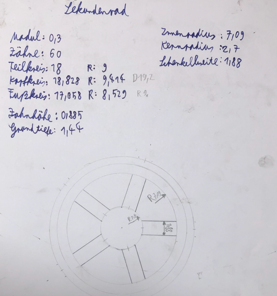
At a minimum, the number of teeth and the module should be known, as should the
dimensions of the pinion onto which the wheel is to be riveted. Then begin
calculating the missing dimensions:
- Pitch-circle diameter = module × number of teeth
- Addendum-circle diameter = (number of teeth + 2.76) × module
- Root-circle diameter = (number of teeth - 3.14) × module
- Tooth height = (addendum-circle diameter - root-circle diameter) ÷ 2
- Width of the tooth space at the root = tooth height × 1.627
- Inner radius = root-circle diameter - 2 × width of the tooth space at the root
- Hub radius = pitch-circle radius of the pinion × 1.5
- Spoke width = (3 ÷ 7) × (inner radius - hub radius)
Once all the values have been calculated, a drawing is produced at
a suitably enlarged scale.
Making the wheel
Work can then begin. First, a piece of brass sheet is roughly cut to size and ground on both sides to relieve stresses in the material and obtain flat surfaces.
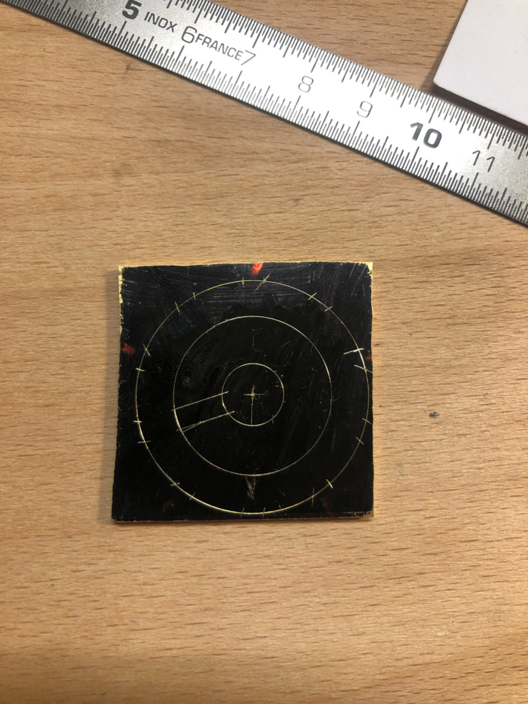
The wheel is then marked out with dividers, a scriber and a steel rule. First, the sheet is coloured black with a felt-tip pen to make the scribed lines easier to see. To locate the dividers cleanly, first
make a centre-punch mark.
To set the dividers as accurately as possible, it helps to first mark the required dimension with a height gauge on
a piece of sheet metal and then pick it up with the dividers.
Once all the circles have been drawn, the spokes must be marked out. This requires further calculations.
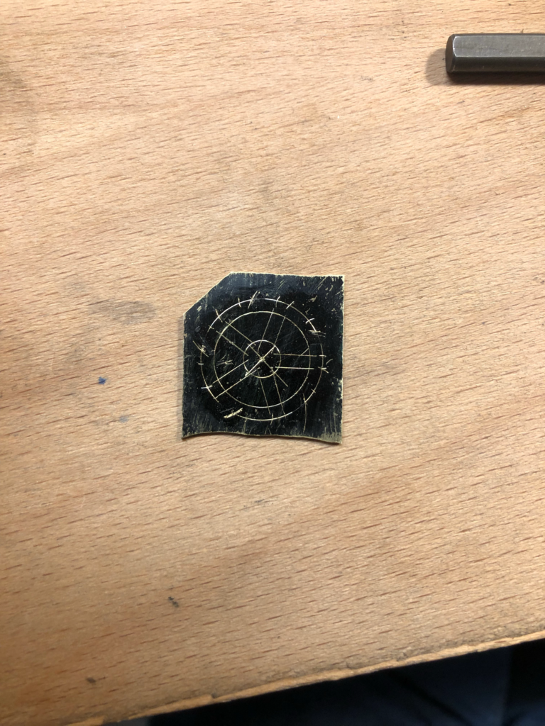
The wheel is to have five spokes. To mark these through the centre, divide the circle into ten equal parts, each of 36 degrees. The cosine rule is used to calculate the distance between two neighbouring points on the circumference. The formula is: X=r^2•r^2–2•r•r•cos(36)
Set the calculated distance on the dividers and start at any point on the circle. Work from one point to the next until the circle closes. If you do not return exactly to the starting point, slightly correct the dividers’ setting and try again from a slightly offset position. Paint over the old marks.
After this step, set the dividers to the spoke width and make a further mark from each point. The points can now be joined with the steel rule and scriber.
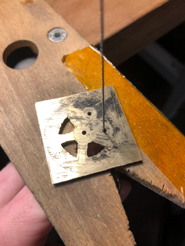
Next, drill the holes: first a small hole in the centre and one in each space between the spokes. Then begin sawing out the rough shape. Leave a generous allowance, especially around the outside, for turning round and subsequently cutting the teeth.
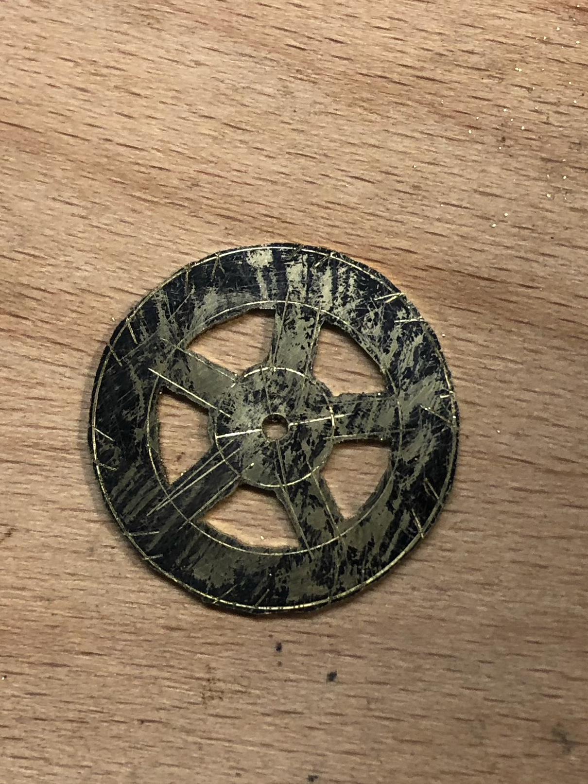
The wheel is then turned round, mounted on a turning arbor or wax chuck. The target dimension should be a good half millimetre larger than the eventual addendum-circle diameter. The spokes are then brought to their final shape using progressively finer files. Measurements can be checked with a vernier caliper, but an evenly proportioned appearance is more important.
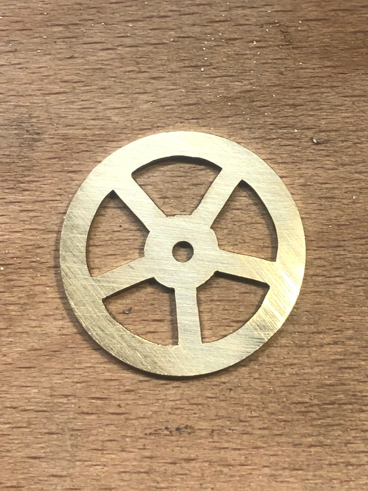
After this step, grind both sides of the wheel again to remove the remaining scribed lines, then deburr all the edges.
It is advisable to make several additional brass discs with the same outside diameter to provide test pieces for cutting the teeth.
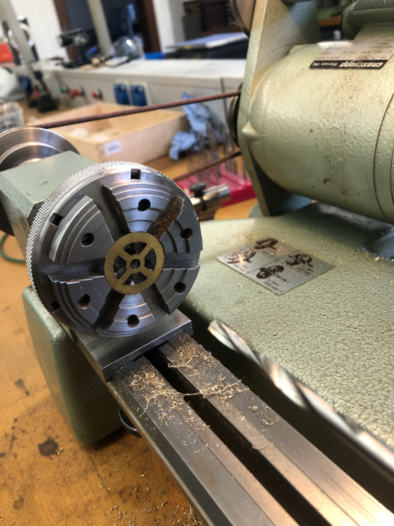
Now clamp the wheel in the lathe’s six-jaw chuck and bore the central hole to the pinion’s pitch-circle diameter, if the wheel is to be riveted onto a pinion. Work in the smallest possible increments to avoid pulling the wheel out of the chuck.
Then deburr the hole on both sides.
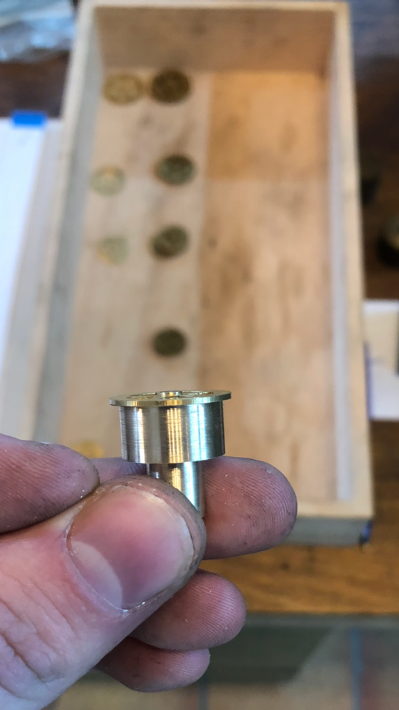
A mounting arbor must be turned before cutting the teeth. It needs a shoulder at one end to fit a collet and, at the other end,
a shoulder onto which the wheel slides without play. The middle section should be
slightly smaller than the root-circle diameter. As a counterpart to this arbor, turn a bell-shaped piece whose outside diameter matches the largest
diameter of the mounting arbor. It also needs a recess and
a central hole slightly larger than the hole in the wheel.
The machine must now be set up. First, consult the table to determine the change wheels needed for the required tooth count. Next, select a cutter matching the desired module and covering the relevant tooth-count range. A sleeve may now need turning to hold the cutter in the machine. Once the cutter and change wheels are fitted, use a fixed centre through the designated hole to check that the cutter is centred. A white sheet of paper increases the contrast. Clamp the mounting arbor in the lower collet, place the wheel on it, and clamp it firmly with the bell-shaped holder and a revolving centre.
Cutting can begin. Use conventional milling and lubricate the cutter with milling paste. First, feed it in until the tooth tips are cleanly formed. Then
cut the complete wheel and measure its diameter. You can now
determine how much further to feed in to obtain the required
addendum-circle diameter.
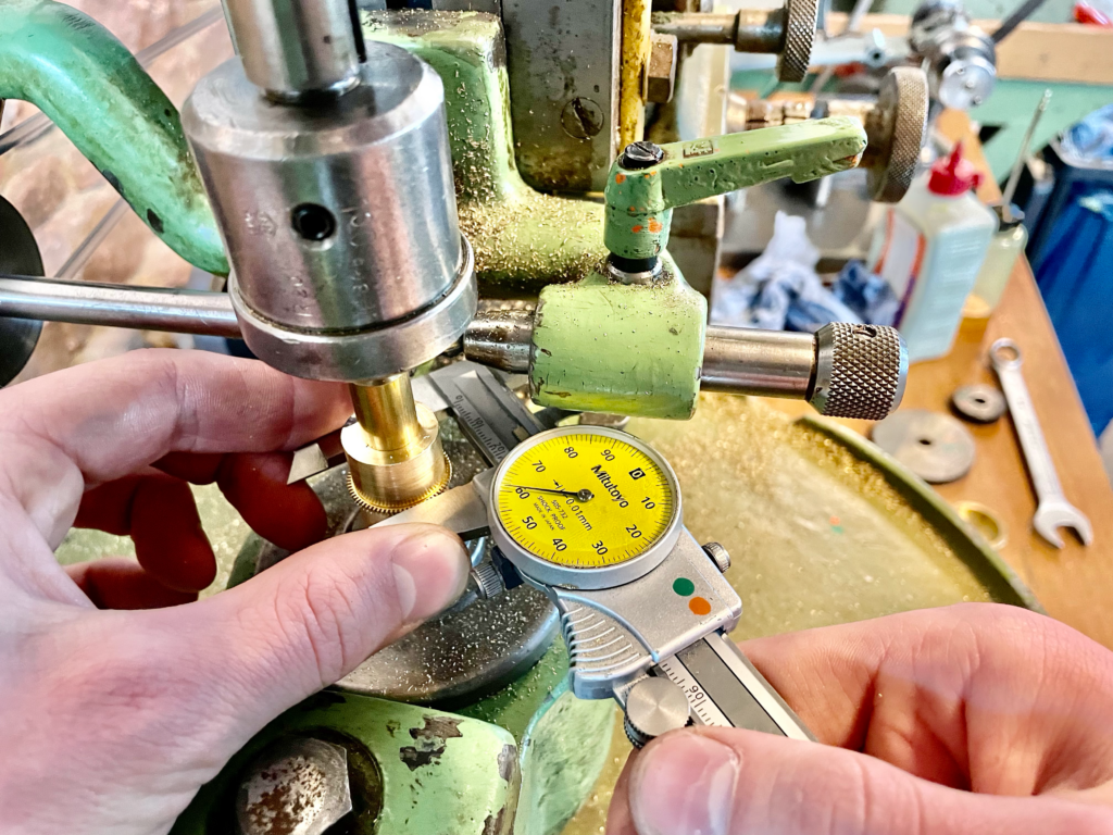
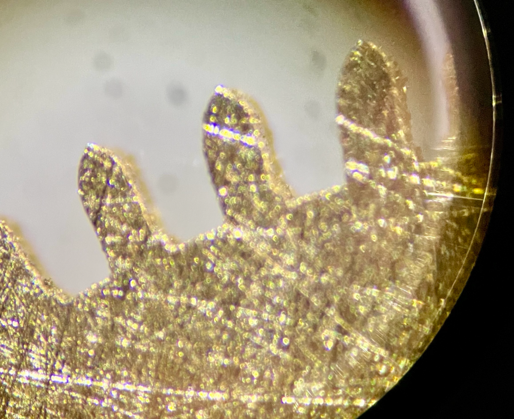
Once all the teeth have been cut again, the desired diameter should have been reached. Remove the wheel and deburr it on an abrasive plate. Under the microscope, check whether the teeth are correct or whether the machine needs further fine adjustment.
If everything is correct, the remaining blanks can have their teeth cut in one pass
each. Several blanks can also be clamped together in a stack.
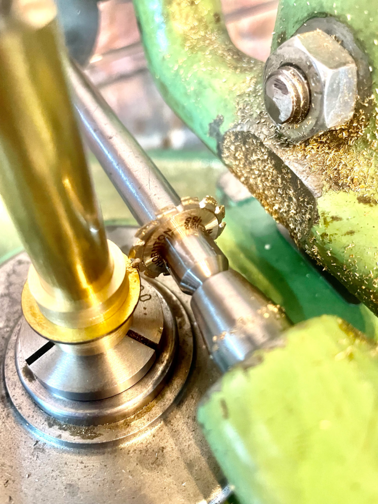
Once cutting is complete, all the wheels are ground flat and
given a decorative finish.
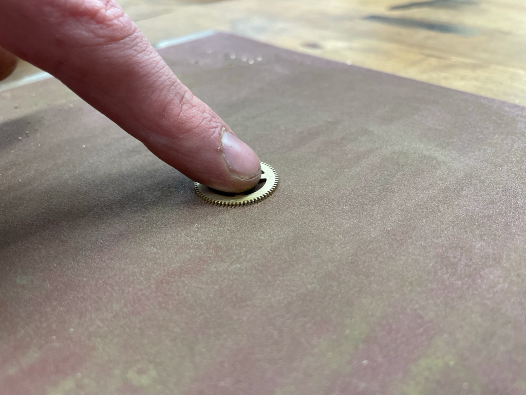
For this, they are either clamped with a
protective film in the six-jaw chuck, or attached with double-sided tape to
a wax chuck. Centre the wheel using the drilling tailstock.
Start the lathe and use abrasive paper to apply a circular-grained
finish. Clean the wheels in the ultrasonic bath. Use a
specially ground oiler to deburr each tooth individually.
Finally, clean the wheels once more.