The Swiss lever escapement – Part 3: Master watchmakers
Part 3 · Master
A closer look: terms, angles, draw, safety clearances
Part 3 takes the subject further for master watchmakers and assumes the workshop part. But why does a finding look the way it does, and what do the various textbooks say about it? We calculate how an adjustment works out in numbers, go through exam cases and establish what the timing machine actually measures.
We have already seen in the first two parts that the textbooks do not say the same thing everywhere. This is rarely due to a mistake. There were different traditions and schools that divided up the escapement differently and named its quantities differently. Where this matters for the workshop, we set the positions side by side. All figures for our model come from the same calculation as the animations. Angles at the pallet fork are given in lever degrees about the pallet centre, angles at the escape wheel in degrees about the centre of the escape wheel, and angles at the balance in balance degrees about the balance staff.
Terms that are often confused
Many workshop disputes are therefore really questions of terminology, because two books use the same word for different quantities. The most common cases are listed in the table.
The best-known example is horn clearance. Brinkmann and the Pforzheim handouts use this name for fork play at the instant of drop, that is, the play between the fork corners and the impulse pin at the instant the tooth drops. Following the Bulova School of Watchmaking, we keep it separate from horn clearance (Chain of safety features and clearances). Only this play depends on the position of the pallets, which is why Brinkmann logically corrects his “horn clearance” via the pallets.
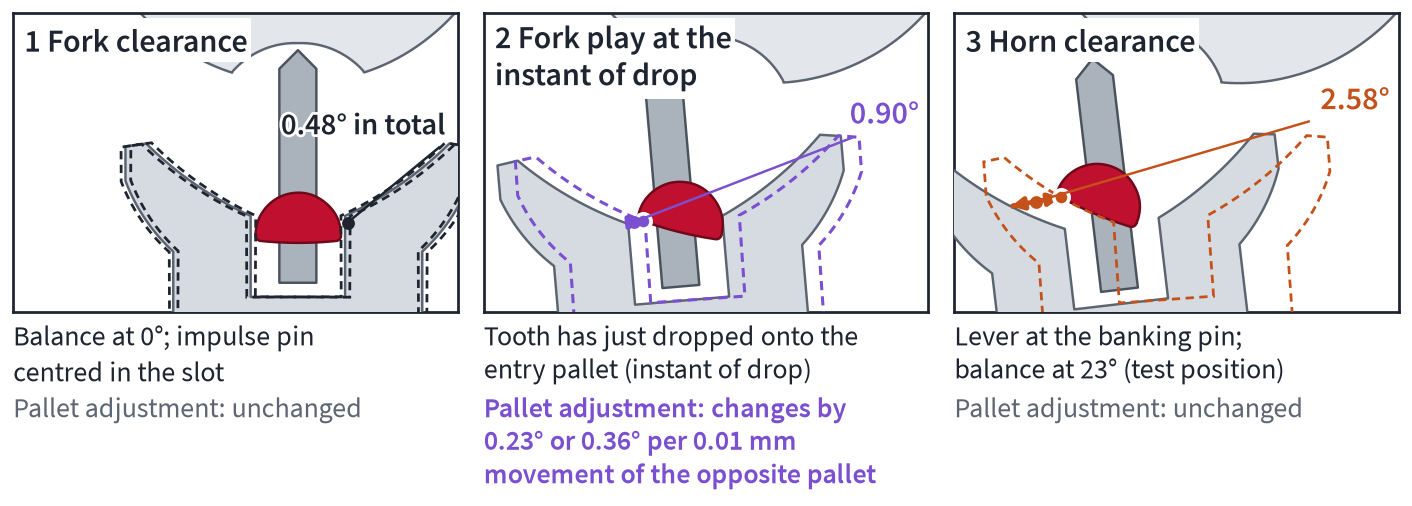
Three clearances at the impulse pin according to Bulova. Only fork play at the instant of drop changes when the pallet stones are moved.
In this article | Also called elsewhere | Where |
|---|---|---|
Fork clearance | Gabelspiel, Gabeleinschnittluft | Röseler; Pforzheim question set |
Horn clearance, guard pin clearance | Hörnerspiel, Messerspiel | Exam questions, Theorie der Uhrmacherei |
Depth of lock | Gangtiefe (in Schultz, by contrast, the drop lock), Festhalteruhe, totale Ruhe, often just “Ruhe” | Bossart, Schultz; Würzburg, Pforzheim question set; Theorie der Uhrmacherei |
Drop lock | “Ruhe” with the symbol δ | Röseler |
Draw angle | “Zug” for the safety provided by deeper lock; “Zugwinkel” for the undercut of the club teeth (24°) | Pforzheim, Würzburg; trade journals |
Drop, run to the banking | “Nachfall”, sometimes for the drop, sometimes for the run to the banking | Schultz; Röseler after Schirmer |
Inside and outside drop | named after the pallet at which the drop begins or ends | Schultz, Würzburg, Saunier |
Impulse pin | “Hebelsteine”, “Hebesteine” for the pallets | translated manufacturers' documents |
Run to the banking | “Hemmung mit verlorenem Weg” for an impulse in only every second half-oscillation (French à coup perdu; better: verlorener Schlag) | trade journal |
Amplitude | one oscillation counted as two amplitudes, the quarter oscillation called “Halbschwingung”; English “turns” count the whole arc | trade journals; Wilkinson |
Lift angle | “Hebewinkel” explained as the sliding path of the tooth (balance angle and sliding path confused) | trade journal |
The lift angle is the angle through which the balance turns from the first contact of the impulse pin with the fork until the drop. The sources use it to mean sometimes the engagement range of the design, sometimes the acoustically measured range, the typical manufacturer's value or the setting on a particular timing machine. How these values differ on the model, the movement and the timing machine is covered in The lift angle in more detail.
Fork travel and lever travel are just as often confused. Fork travel is the angle through which the pallet fork turns while the fork is in engagement with the impulse pin, that is, unlocking plus impulse. On the adjusted model this is 11.8° and 11.9° respectively. Lever travel runs from banking pin to banking pin and additionally includes the run to the banking, on the model 13.6°. Figures such as “lever travel 10°” or “3 : 1” in the textbooks usually mean the fork travel. The lever ratio, that is the ratio of lift angle to fork travel, also refers to it, in the model 34.55° : 11.82° ≈ 2.9.
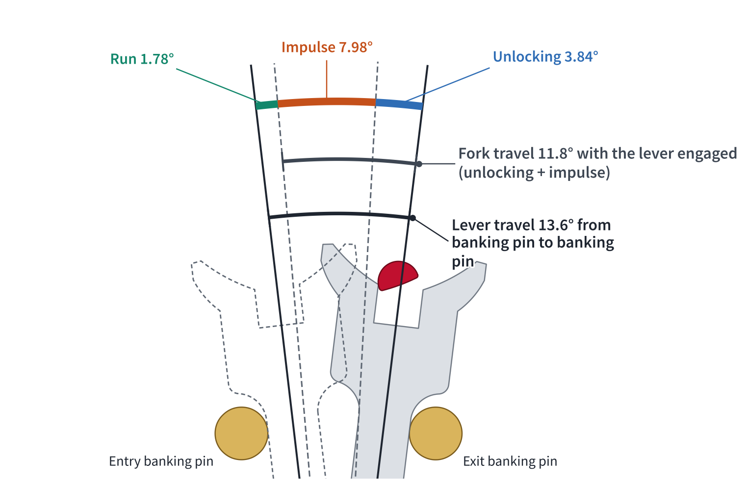
Fork travel 11.8° and lever travel 13.6° on the adjusted model. The difference is the run to the banking.
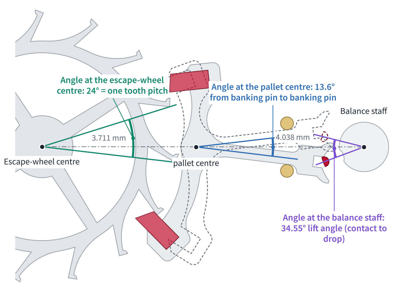
Every degree value applies only to its own pivot point, that is, to the pallet centre, the centre of the escape wheel or the balance staff.
The sources also divide up the phases differently. The Theorie der Uhrmacherei combines drop, run to the banking and supplementary arc as “safety”. The Pforzheim course notes and the phase sheet of the final examination recognise four phases and count the run to the banking as part of the drop. Bulova describes six steps, and Soguel distinguishes two impacts in the impulse and has no separate locking phase. In substance they do not contradict each other, because they all describe the same sequence, only divided up more or less finely.
The angles in step
The balance, pallet fork and escape wheel pass through their sections at the same time, but with very different angles. During unlocking, the balance turns the pallet fork away from the banking pin, and the escape wheel recoils slightly. During impulse, the escape wheel turns forwards and drives the pallet fork. The pallet fork in turn gives the balance its impulse (Bossart). The table sets our adjusted model alongside the values in the Theorie der Uhrmacherei for an escape wheel with 15 teeth.
Phase | Balance, model | Balance, textbook | Pallet fork, model | Pallet fork, textbook | Escape wheel, model | Escape wheel, textbook |
|---|---|---|---|---|---|---|
Unlocking | 10.4 / 10.2 | ≈ 8 | 3.84 / 3.78 | 2–4 | −0.47 / −0.39 | −0°15′ |
Impulse | 24.15 / 24.7 | ≈ 30 | 7.98 / 8.14 | ≈ 10 | 10.30 / 10.32 | ≈ 10°30′ |
Drop | Supplementary arc | Supplementary arc | – | – | 1.80 / 2.03 | 1–2 |
Run to the banking | Supplementary arc | Supplementary arc | 1.78 / 1.68 | 0°30′–1° | 0.20 / 0.26 | – |
Total | 34.55 / 34.9 | ≈ 38 | 13.60 / 13.60 | 12–20 | 11.8 / 12.2 | 12 |
The totals can be checked. From banking pin to banking pin, the pallet fork turns through the unlocking, the impulse and the run to the banking of the opposite side, so on the model through 3.84° + 7.98° + 1.78° = 13.60° and 3.78° + 8.14° + 1.68° = 13.60° respectively. Measured directly between the banking pins, it is 13.62°. In the table, the unlocking, at 3.78° on entry and 3.84° on exit, is slightly larger than the depth of lock of 3.26° and 3.36° respectively. Both values are correct, because they are simply delimited differently. The depth of lock ends exactly when the tooth's locking corner, the edge at its locking face, stands at the pallet's locking corner, whereas the unlocking ends slightly later in the model's motion sequence.
The textbook rule that the escape wheel turns through half a pitch per half-oscillation applies only on average. In one half-oscillation it turns through 11.8°, in the other through 12.2°, together 24.0°, exactly one pitch.
At 3.26°/3.36°, the depth of lock of our model is well above Bossart's 1¾ to 2°. This is not a contradiction, because in the textbook the degree values for lock are design angles, whereas the workshop rule refers to a quarter of the length of the impulse face (Drop-lock point, depth of lock, run to the banking).
Today's wristwatches work with a larger lift angle and greater lever travel than the textbook's pocket watch:
Type | Lift angle | Lever travel | Source |
|---|---|---|---|
Pocket watch, 15 teeth | 30–36° | 10–12° | Bossart, Brinkmann, Helwig, Jendritzki; Wilkinson |
Glashütte layout | 30° | 10° (fork travel) | Textbook sheet of unknown origin |
“small lever watch” | 50° | 12° (fork travel) | same sheet |
Mass-produced movement 18,000 vph (Unitas 6497/6498) | 44° | – | Manufacturer's specification |
Swiss ébauches, standard escapement and related designs | usually 52°, up to 54° | – | ébauche data sheets |
Wristwatch | 49–54° | 12–20° from banking pin to banking pin | Manufacturers' specifications; Theorie der Uhrmacherei |
Series movement at 3 Hz, centre distances as in the standard escapement | ≈ 46° (calculated) | 13.2° from banking pin to banking pin, ≈ 11.7° in engagement | Röseler |
Our model, adjusted | 34.55° / 34.9° | 11.8–11.9° in engagement, 13.6° from banking pin to banking pin | Model |
The smaller the amplitude, the larger the share of the arc in which the escapement is engaged. With a 35° lift angle and 280° amplitude, that is a good 6% of a half-oscillation; at 140°, it is already 12.5%. In terms of time, the share is even smaller, because the balance moves fastest while engaged. At 4 Hz, 52° lift angle and 280° amplitude, the escapement is engaged for around 7.4 ms of 125 ms (6%); on our model, at 18,000 vph and 35° with 280°, for around 8 ms of 200 ms (4%).
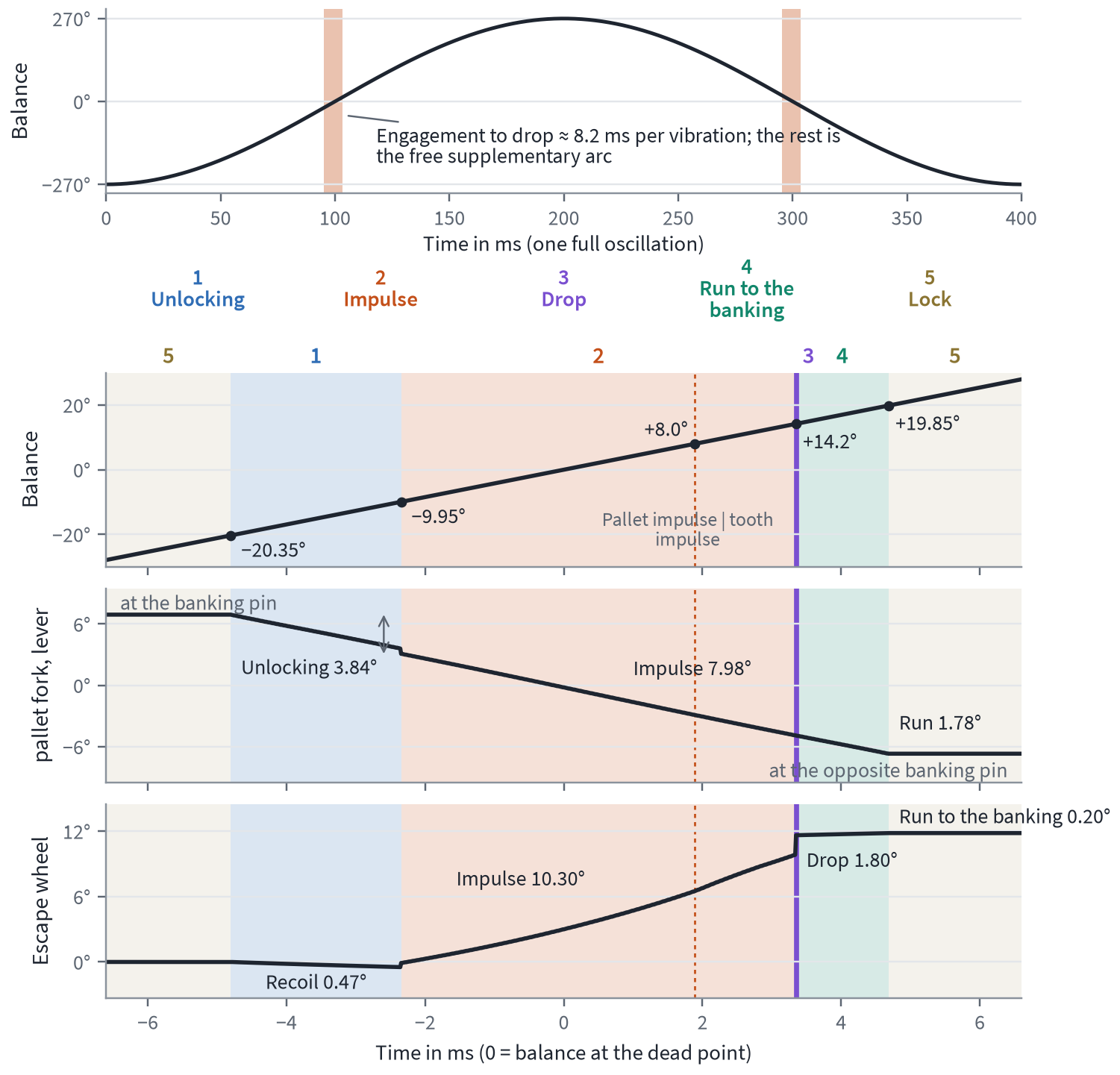
Angles of the balance, pallet fork and escape wheel over time (2.5 Hz, amplitude of 270° assumed). The top shows one full oscillation, and below it an enlarged half-oscillation with the five phases.
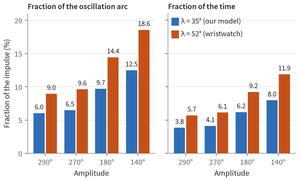
Share of the impulse in the arc and in time for a 35° lift angle (our model) and 52° (typical wristwatch).
What really happens: the dynamics behind the slow motion
The animations are calculated quasi-statically. Each frame arises from the contacts between the components, but without inertia. The position of every component is correct, but timings and impacts are idealised. In the watch, things are wilder.
In his dissertation, Röseler evaluates high-speed recordings. After unlocking, the tooth flies freely and only strikes the impulse face about a third of the pallet width further in. At the changeover from pallet lift to tooth lift, contact is briefly lost. Such recordings also show that after the drop the tooth bounces about twice on the locking face, like a dropped ball, before it comes to rest. How often and how hard it bounces depends on the geometry, the force and dirt. A slow-motion film reported by Reuer in 1968 also shows a fork that flutters throughout the engagement.
According to Helwig, the pallet fork strikes the banking pin with its lever arm and rebounds. The drop and the banking-pin impact follow each other so closely that they sound like a single impact (Helwig, Theorie der Uhrmacherei), and according to Bossart the impulse pin leaves the fork before the pallet fork has completed the run to the banking. Soguel divides the impulse into two sections, each beginning with an impact. First the tooth strikes the impulse face, and the pallet fork passes through the fork clearance. Then the other flank of the fork strikes the impulse pin, and only from this moment does the pallet fork drive the balance. During the drop, the escape wheel turns practically freely, and to counter the force of the impact Helwig recommends a sprung escape pinion for precision watches.
In our model things happen differently. After the drop, the fork pushes the impulse pin on by a further 5.65° or 5.25° of balance angle, depending on the half-oscillation, which at 280° amplitude is around 1.2 to 1.3 ms, and it only releases the impulse pin once the pallet fork rests against the banking pin. This is due to the geometry and not to the absence of inertia, because the pallet fork could only be faster than the impulse pin if it pushed the much more inert balance along with it. This does not contradict the observations in the literature. They show what elastic, bouncing components do in the watch, and a rigid model cannot reproduce that. The consequences for the timing machine are covered in The lift angle in more detail.
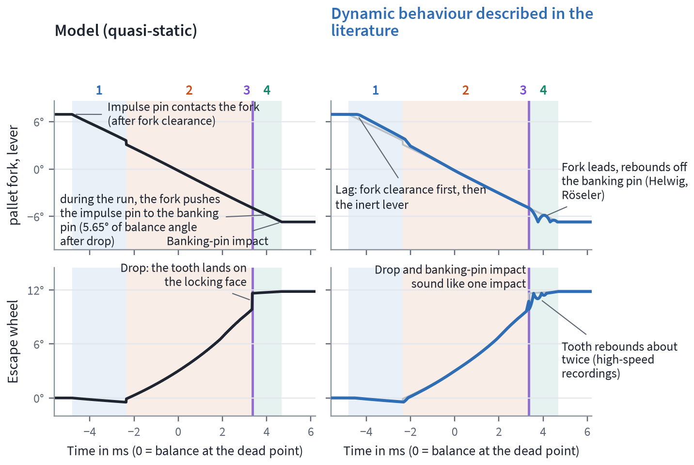
Pallet fork and escape wheel over time in the model and in the dynamic sequence according to the literature, with rebound at the banking pin and bouncing of the tooth. Schematic.
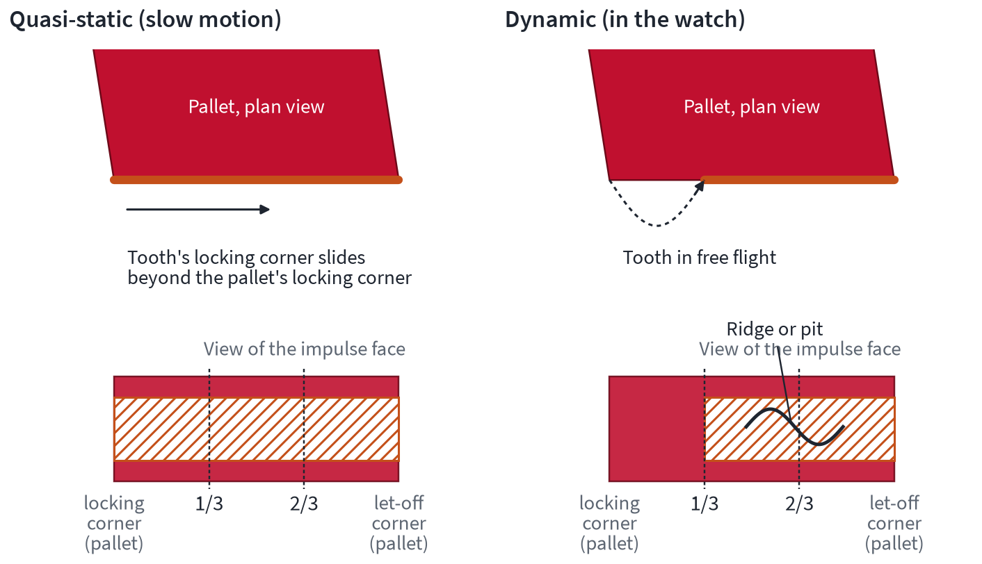
In running, the tooth strikes the impulse face about a third of the pallet width further in than in the animation; that is where the wear track begins. A worn pallet is nevertheless always a fault: perhaps not an escapement fault, but serious wear that changes the angles in the sequence and increases friction. Often there is also a ridge or pit in the wear track at the point where the pallet fork passes the impulse on to the balance. This is best repaired with a new pallet or by repolishing. Schematic.
An old point of dispute is connected with the dynamics, namely whether the run to the banking should be as small as possible. Bossart and Playtner say it should, because it lengthens the unlocking. Röseler calculates about 7° more amplitude for a smaller run to the banking, and on series movements a smaller run to the banking and a smaller fork clearance together brought 10 to 15° more. The other side sees the run to the banking as a necessary reserve. Without it, with a longer tooth or an escape wheel that is out of round, the pallet fork reaches the banking pin before the tooth has left the impulse face, and the escapement locks up (Pforzheim). Claußen calls it the space for teeth of unequal length, and according to Helwig it damps the rebound of the pallet fork at the banking pin in simple watches. Reuer advises adjusting it carefully instead of helping out with a stronger mainspring.
According to the workshop rule, the run to the banking is about half the depth of lock, on the model 1.78°/1.68°. Bossart, by contrast, gives only 15 to 30 minutes of arc. For the workshop this means that you set the run to the banking as large as necessary, not as small as possible.
Draw in more detail: effective draw, friction angle, measurement
Draw only pulls the pallet fork against the banking pin if the draw angle is larger than the friction angle, because otherwise friction holds the tooth fast on the locking face. With a coefficient of friction of 0.15 for oiled steel on ruby (Eisenegger), the friction angle is 8.5°. Röseler gives coefficients of friction of 0.1 to 0.2, and Bossart and Brinkmann put the friction angle at 9°. A collection of formulas without a source reference, by contrast, gives 0.04 to 0.05, that is 2.3 to 2.9°. With the usual 12 to 16° of draw angle, the draw condition is met in both cases, but for the energy lost through friction during impulse the difference matters a great deal (Worked example B: where the two thirds go).
During unlocking, the draw angle does not stay the same. The effective draw, that is the draw angle in the lever position at the time, increases at the entry pallet by the whole locking angle and decreases at the exit pallet by the same amount. Bossart shows this with an example using an exaggerated 5° of lock, in which 13° on entry becomes 18° and 15° on exit becomes 10°. That is why the exit pallet is given the larger draw angle, according to Röseler larger than that of the entry pallet by exactly the drop lock (Forces at the pallet and fork). On the model this applies only at the banking pin, where the difference is 5.4°. At the pallet's locking corner it is the other way round.
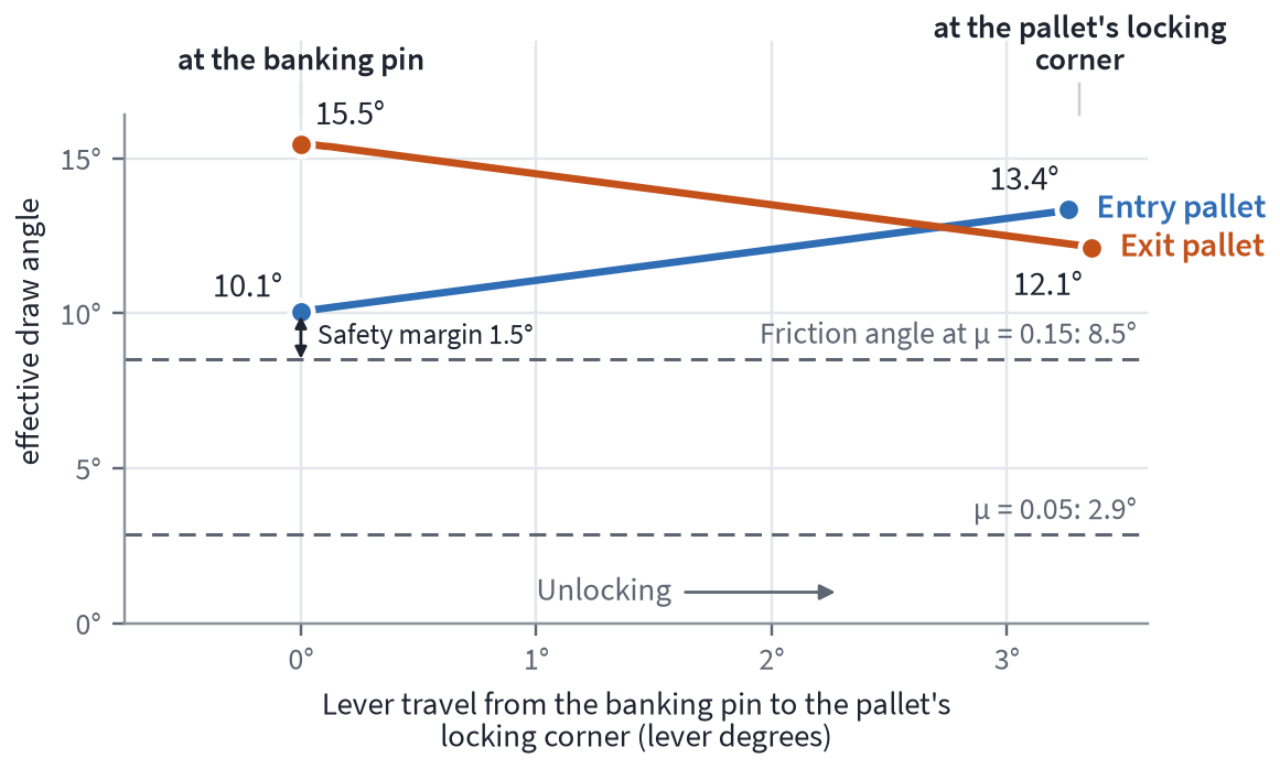
Effective draw angle over the lever angle on the adjusted model. During unlocking, it rises on entry from 10.1° at the banking pin to 13.4° at the pallet's locking corner and falls on exit from 15.5° to 12.1°.
The sources disagree on whether draw becomes stronger if you pull a pallet out. According to Pforzheim and Würzburg it does, if you pull the pallets out or adjust the banking pins outwards. Smith, by contrast, advises pushing the pallet in slightly if draw is too weak, that is, in the opposite direction, but does not say which pallet he means. A third answer comes from the geometry, which distinguishes between pallet and banking pin. On the adjusted model, the effective draw angle with the pallet fork against the banking pin is 10.1° on entry and 15.5° on exit. If you move a pallet by 0.01 mm, this value practically does not change (less than 0.01°), because the locking face slides along its own direction. Only the pallet's locking corner moves with the pallet, and the draw angle at the pallet's locking corner changes by 0.30° per 0.01 mm. Pulling out makes it larger on entry and smaller on exit, and on exit the pallet's locking corner is the point with the least draw on the locking face. At the banking pin, of all the adjustments only the banking changes the draw angle. If you open it by a further 0.25°, it falls on entry by 0.24° to 9.8° and rises on exit by 0.24° to 15.7°. Deeper lock via the banking pins therefore makes the effective draw smaller on entry and larger on exit.
The Pforzheim handout explicitly uses “draw” to mean the safety provided by deeper lock and not the draw angle, and the Würzburg master course is very probably to be understood the same way. I myself trained in Pforzheim and was taught to use draw as the word for the force that pulls the pallet fork against the banking. The Chamber of Crafts exam question of whether draw on entry becomes stronger if you adjust the entry banking pin outwards is therefore answered in two parts: depth of lock and safety increase, but the effective draw angle on entry decreases.
Source | Entry | Exit | Note |
|---|---|---|---|
Saunier (1855) | 15° | 12° | from the wheel radius |
Großmann (1884), Playtner (1910), Wilkinson (1916) | 12° | 12° | |
Dietzschold (1905) | 12° | 13½° | from the perpendicular to the lever radius |
Bossart (1950) | 13°30′ | 15° | range from 9° to 15° |
Würzburg master course | 12°30′ | 13°30′ | |
Jendritzki | 12° | 13.5° | in the illustration 12°/14.5° |
Theorie der Uhrmacherei | 13–16° | range | |
Röseler (2015) | ζ | ζ + drop lock | design rule |
Eisenegger, Uhrenkonstruktion (2011) | 15° | 13° | drawing with 15 teeth |
Nivarox 20.3 (in Eisenegger) | 15° | – | from the wheel radius, modern 4 Hz reference design |
Our model, adjusted, at the banking pin | 10.1° | 15.5° | Contact point of the tooth's locking corner with the pallet fork against the banking pin, from the perpendicular to the lever radius; from the wheel radius 9.9°/14.7° |
Our model, adjusted, at the pallet's locking corner | 13.4° | 12.1° | Crosshairs through the pallet's locking corner and the pallet centre, as in Bossart |
Like the Theorie der Uhrmacherei and Bossart, we measure from the perpendicular to the line from the pallet centre to the measuring point; Saunier and Nivarox, by contrast, measure from the wheel radius. The measuring point matters as well. Bossart measures with the crosshairs at the pallet's locking corner, whereas draw on the lock acts at the contact point of the tooth's locking corner when the pallet fork rests against the banking pin. On the model, the values at the two points differ by about the depth of lock, around 3.3°, on entry in one direction and on exit in the other. At the banking pin, the exit has the larger draw angle (15.5° against 10.1°); at the pallet's locking corner, the entry does (13.4° against 12.1°). For every draw angle you therefore have to state which reference line it was measured from, at which measuring point and in which lever position. Playtner, for example, measures with the fork at the banking pin. It is measured with rotatable crosshairs in the microscope (Bossart). You lay one hair through the pallet's locking corner and the pallet centre and take a reading, then rotate the eyepiece until the other hair lies on the locking face, and take a reading again.
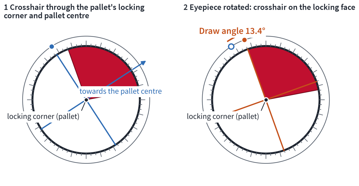
The draw angle is measured with two positions of the crosshairs. The difference between the two readings is the draw angle.
The ladder of safety clearances and the rebanking limit
The safety features work one after another, and each must take effect before the tooth leaves the locking face. Bossart's rules give a ladder of safety clearances: run to the banking ≤ inner horn clearance ≤ guard pin clearance < outer horn clearance < depth of lock. In addition, according to Würzburg, the depth of engagement of the impulse pin must be greater than the horn clearance. What this means in the workshop is set out under Depth of engagement: along the whole horn, no shock may bring a tooth onto the impulse face.
Bossart justifies the order by the fact that the impulse pin leaves the fork before the end of the run to the banking (on our model only at the banking pin) and must not rub against the horn in doing so. In the event of a shock, the pallet fork gives way as far as the guard pin or, if the guard pin is just in the passing hollow, as far as the horn, and in both cases the tooth must remain on the locking face. Bossart sets the inner horn clearance below the guard pin clearance because the distance from the guard pin to the safety roller varies with every runout error.
The sources differ on the size of guard pin clearance. According to Helwig and the Theorie der Uhrmacherei, it should be large enough that about half the lock remains with the guard pin in contact. Bulova requires it to be slightly smaller than the lock, the Pforzheim question set gives ⅔ of the depth of lock, Wilkinson requires it to be smaller than the drop lock, and Röseler at most as large as half the unlocking angle. Würzburg and Brinkmann require a horn clearance that is greater than the guard pin clearance. According to the Würzburg reasoning, the impulse pin should reliably find its way into the fork after a shock, so what is meant is the outer horn. The US service manual TM 9-1575, according to which guard pin clearance is half the horn clearance, is an outlier.
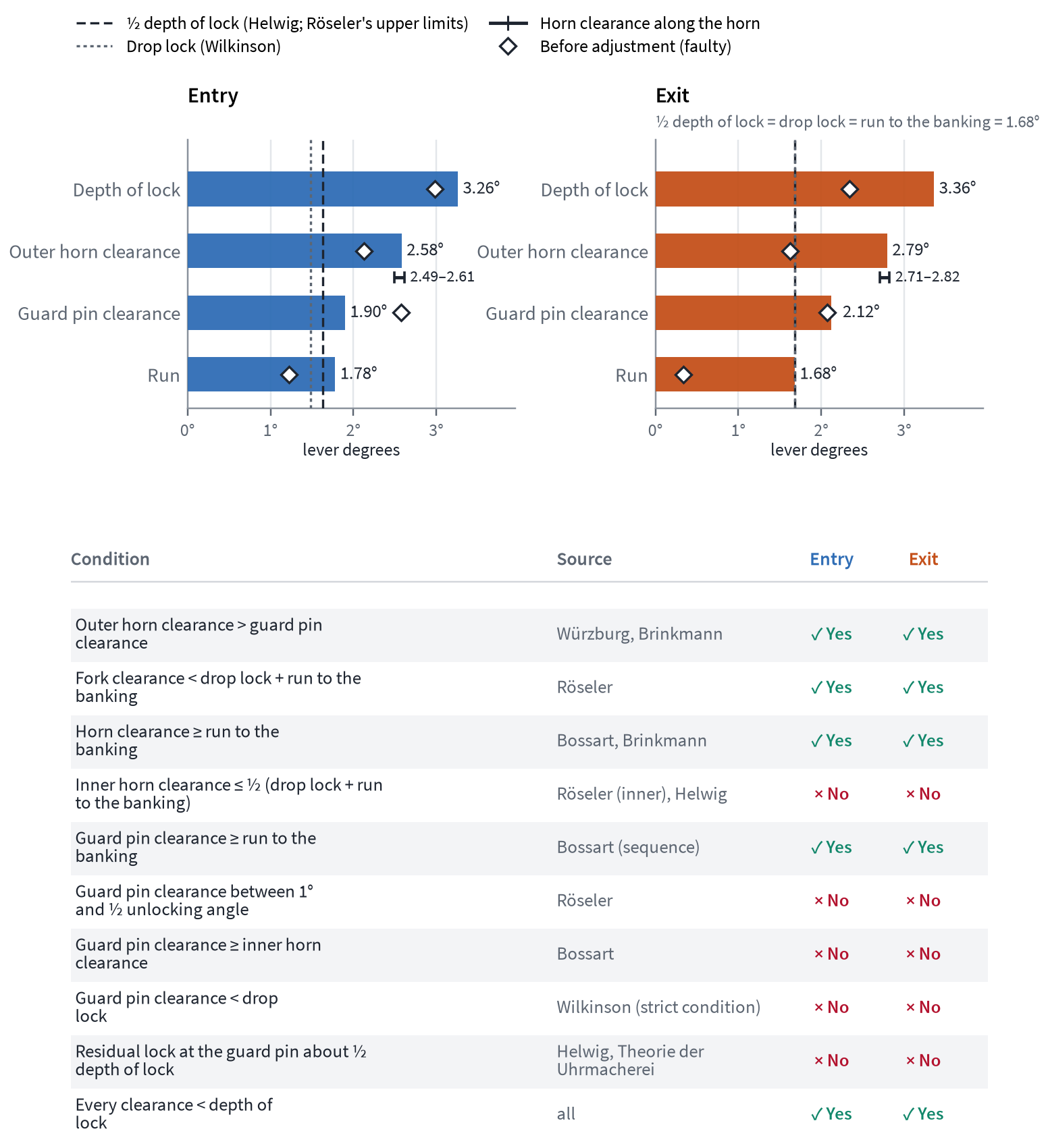
Ladder of safety clearances on the adjusted model, with the limits given in the textbooks.
On entry on our model, the run to the banking, at 1.78°, is larger than half the depth of lock, at 1.63°. If you make the guard pin clearance there at least as large as the run to the banking, less than half the lock remains with the guard pin in contact, and Röseler's upper limit is also exceeded, because half the unlocking angle, calculated with the depth of lock, is likewise 1.63°. On exit, the run to the banking, half the depth of lock and the drop lock meet at exactly 1.68°. Wilkinson's strict requirement to keep guard pin clearance smaller than the drop lock cannot be achieved with the workshop rule (⅛ and ¼), because guard pin clearance must leave at least the run to the banking free, and the drop lock is not larger than the run to the banking (on entry 1.48° against 1.78°).
On entry, our model follows Bossart's chain, because guard pin clearance there, at 1.90°, is just above the run to the banking. On exit it is 2.12°; the difference is determined by the banking pins. When the guard pin rests against the safety roller, 1.36°/1.24° of lock remains, around 0.4 of the depth of lock. For this, the guard pin has been moved forward by 0.040 mm and the passing hollow of the safety roller cut out so deep that at least 0.019 mm of clearance remains in running. Without the advanced guard pin, only 0.25°/0.13° of lock would remain. This is our example of a guard pin that is too short.
In the test position, horn clearance, at 2.58°/2.79°, is above the guard pin clearance, and along the whole horn it is at least 2.49°/2.71°. That is how it must be, because the outer horn clearance must be greater than the guard pin clearance. If a shock hits the watch shortly before the impulse pin swings into the area of the horn, the guard pin is still resting against the safety roller, and the pallet fork has given way by the guard pin clearance. If horn clearance were smaller, the impulse pin would strike the horn. On the model, 0.59° still remains between horn and impulse pin in this case, on both sides. The textbook sequence “inner horn clearance at most equal to guard pin clearance”, on the other hand, is not met by our model. This is not critical, because when the horn rests against the impulse pin, at least 0.65°/0.54° of lock remains, and the horn catches the impulse pin first with its tip, then with its curve, and never with the fork corner. I set the guard pin nice and small but distinct, because it still plays its part at the start of unlocking too.
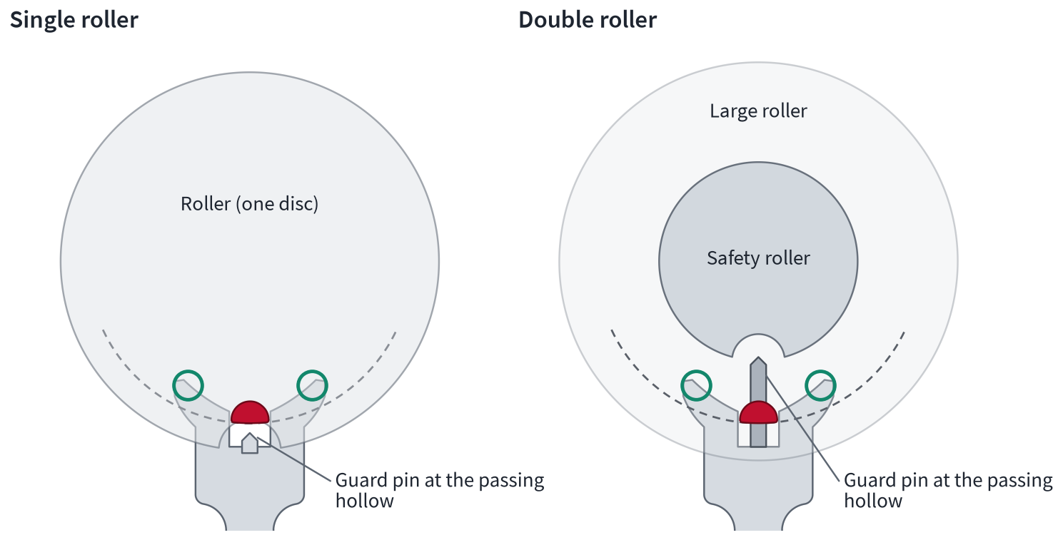
Single roller and double roller, with the handover from the guard pin to the horn.
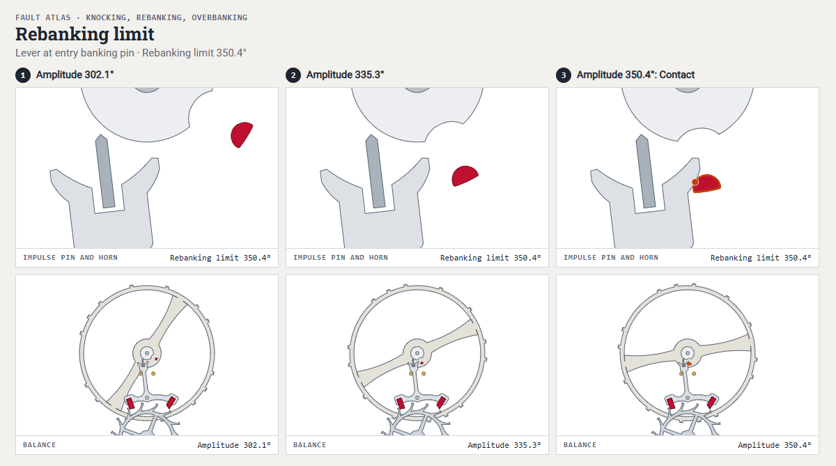
According to the textbook formula, rebanking begins as soon as the amplitude reaches 360° minus half the lift angle minus the horn overlap. Without horn overlap, this would give around 342° at a 35° lift angle and 334° at 52°. Our model only rebanks from around 350°: with the pallet fork against the entry banking pin from 350.4°, against the exit banking pin from 351.0°. When the pallet fork rests against the pin, the impulse pin reaches the back of the opposite horn around 9° before the zero position instead of at half the lift angle, around 17°. In the formula, this acts like a negative horn overlap of around 8°. Banking pins opened further push the limit out, by around 3° per lever degree. Weger warns from about 300°, Berner and the WOSTEP course notes on fine regulation from 315°, Pforzheim and Witschi from around 330°. Manufacturers usually set the limit at 300 to 320° (ETA, Rolex, Sellita).
 Open animation in a separate window
Rebanking limit: the amplitude increases until the impulse pin strikes the horn from behind.
Key point: Every clearance is smaller than the lock it protects, and the guard pin and horns leave at least the run to the banking free. The outer horn clearance is greater than the guard pin clearance; otherwise the impulse pin strikes the horn after a shock.
Moving the pallet stones in numbers
The rules for moving the pallet stones are in the workshop part under Moving the pallet stones and adjusting the banking. Here we work them through in numbers. We look at how much each quantity changes if you move a pallet by a hundredth of a millimetre or open a banking pin by a quarter of a degree, and how fork play at the instant of drop reveals which pallet you have to move. After that we turn to the order in which you proceed and to exam cases on the simulator. The amounts apply to our model, but the directions of the core rule apply to every Swiss lever escapement.
The effect table
In the Pforzheim handouts, the effect of moving the pallet stones is given as a table that shows only plus and minus. Our series of measurements was calculated on the model before adjustment and puts figures on this effect in steps of 0.005 mm, accurate to about 0.02°.
Quantity | Entry pallet 0.01 mm in | Exit pallet 0.01 mm in | Banking pin on entry opened 0.25° | Banking pin on exit opened 0.25° |
|---|---|---|---|---|
Depth of lock, entry | −0.30 | 0 | +0.26 | 0 |
Depth of lock, exit | 0 | −0.30 | 0 | +0.24 |
Drop lock, entry | −0.30 | −0.26 | 0 | 0 |
Drop lock, exit | −0.36 | −0.30 | 0 | 0 |
Run to the banking, entry | 0 | +0.26 | +0.26 | 0 |
Run to the banking, exit | +0.36 | 0 | 0 | +0.24 |
Inside drop (degrees at the escape wheel) | −0.11 | 0 | 0 | 0 |
outside drop (degrees at the escape wheel) | 0 | −0.04 | 0 | 0 |
lift angle of the vibration in which this side unlocks (degrees at the balance) | −1.2 | −0.85 | +0.75 | +0.9 |
guard pin clearance and horn clearance | 0 | 0 | +0.26 (entry) | +0.24 (exit) |
fork clearance | 0 | 0 | 0 | 0 |
fork play at the instant of drop | −0.34 (drop onto exit), 0 (drop onto entry) | −0.25 (drop onto entry), 0 (drop onto exit) | 0 | 0 |
draw angle at the banking pin (effective on the lock) | 0 | 0 | −0.26 (entry) | +0.24 (exit) |
draw angle at the pallet's locking corner | −0.30 (entry) | +0.30 (exit) | 0 | 0 |
The first thing that stands out in the table is that, within the range examined, moving the pallets has an almost linear effect, out as well as in. If you push the entry pallet in by 0.005, 0.01 and 0.02 mm, its own depth of lock changes by 0.16°, 0.30° and 0.60°; if you push it out by 0.005 mm, by 0.14°. As a rule of thumb, you can remember that 0.01 mm at the pallet amounts to around 0.3° at the lever and about three times as much at the balance.
The calculation also confirms a statement by Bossart: if you move both pallets by the same amount, the drop lock changes about twice as much as the depth of lock. This is because each pallet changes both drop locks, but only its own depth of lock. When our model was adjusted, both pallets were pushed in by 0.005 mm. As a result, the drop lock fell from 1.76°/2.00° to 1.48°/1.68°, whereas the depth of lock fell by only 0.16°/0.14°. The banking pins then brought the depth of lock to 3.26°/3.36°.
A pallet does not, however, act quite equally on the two drop locks. The entry pallet acts slightly more strongly on the opposite side than on its own side (0.36° against 0.30°), the exit pallet slightly more weakly (0.26° against 0.30°). The difference between the two drop locks therefore changes by only 0.04 to 0.08° per 0.01 mm, and in the same direction for both pallets: if you push out, it becomes larger; if you push in, it becomes smaller. So the difference between the drop locks can only be changed in small steps, and the whole lock always shifts with it (One pallet or both? The decision path).
Drop changes mainly at the pallet at which it begins. The entry pallet changes the inside drop by 0.11° at the escape wheel per 0.01 mm, the exit pallet changes the outside drop by 0.04°. Wilkinson describes an opposing effect: if you pull the entry pallet out, the inside drop becomes larger and the outside drop smaller. The model shows the first part too, but not the second. On the adjusted model, the inside drop is 2.03° and the outside drop 1.80°.
Bulova's eight-case table (pallet-stone rule) agrees with the series of measurements in the signs for lock, fork play and run to the banking. If you calculate the same series on the adjusted model, all the signs stay the same. The magnitudes differ by at most 0.02° for the lock quantities, and by up to 0.25° at the balance for the lift angle. If you push the entry pallet in by 0.01 mm on the adjusted model, the values change as follows: depth of lock and drop lock on entry −0.30° each, drop lock on exit −0.38°, run to the banking on exit +0.38°, inside drop −0.11° at the escape wheel, lift angle −1.2° at the balance, fork play for the drop onto the exit pallet −0.36°, draw angle at the pallet's locking corner on entry −0.30°. If you push the exit pallet in by 0.01 mm, the values change as follows: depth of lock on exit −0.30°, drop lock −0.26°/−0.30°, run to the banking on entry +0.26°, outside drop ≈ −0.05° at the escape wheel, lift angle −0.75° at the balance, fork play for the drop onto the entry pallet −0.25°, draw angle at the pallet's locking corner on exit +0.30°. If you open a banking pin by 0.25°, the depth of lock, run to the banking, guard pin clearance and horn clearance on its side each change by +0.24°, the lift angle by around +0.75° at the balance, and the draw angle at the banking pin by −0.24° on entry and by +0.24° on exit. When the pallets are moved, guard pin clearance, fork clearance and the draw angle at the banking pin remain unchanged; when the banking pins are adjusted, drop lock, drop, fork clearance, fork play at the instant of drop and the draw angle at the pallet's locking corner remain unchanged.
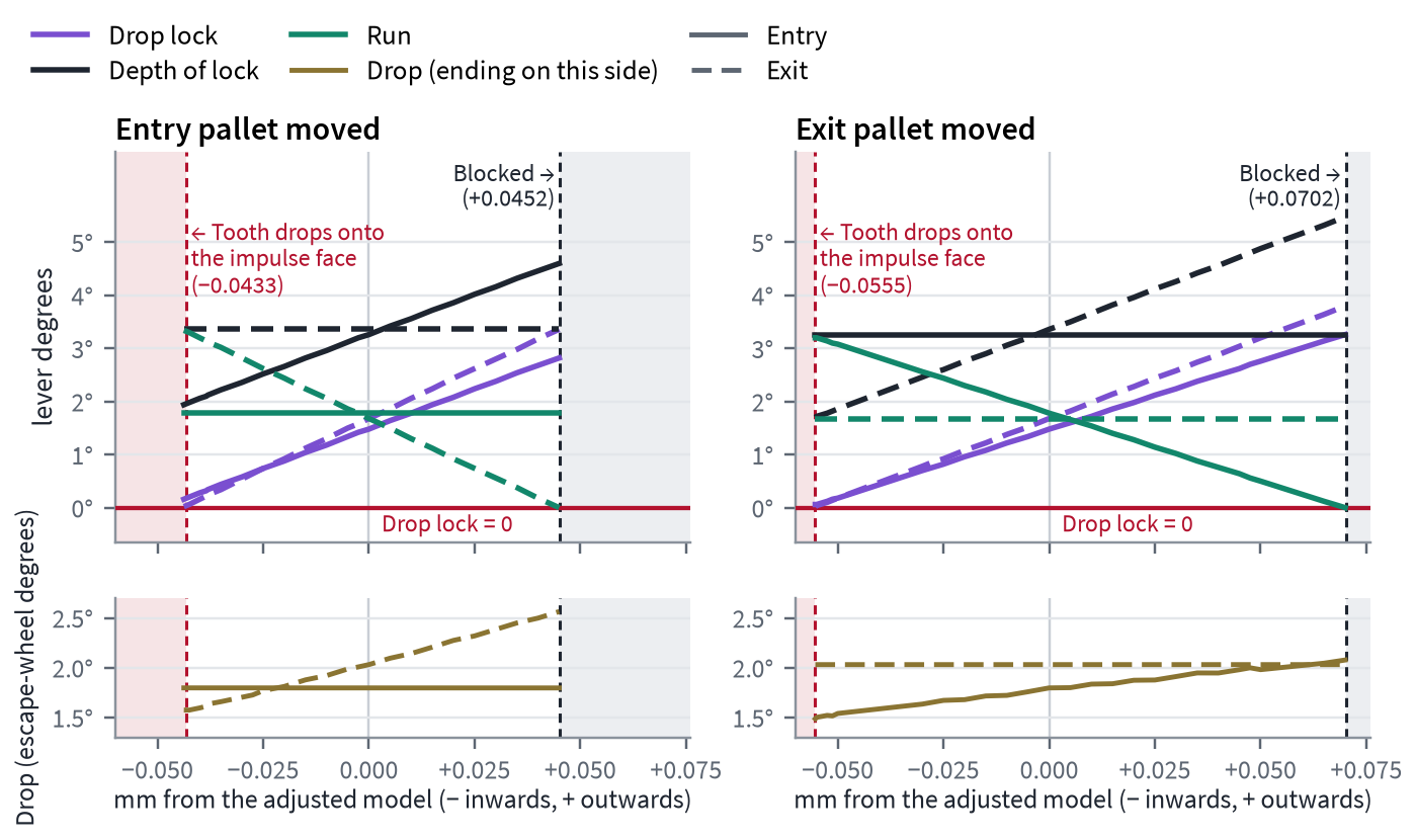
Drop lock, depth of lock, run to the banking and drop plotted against pallet displacement, with the limits “blocked” and “tooth drops onto the impulse face”.
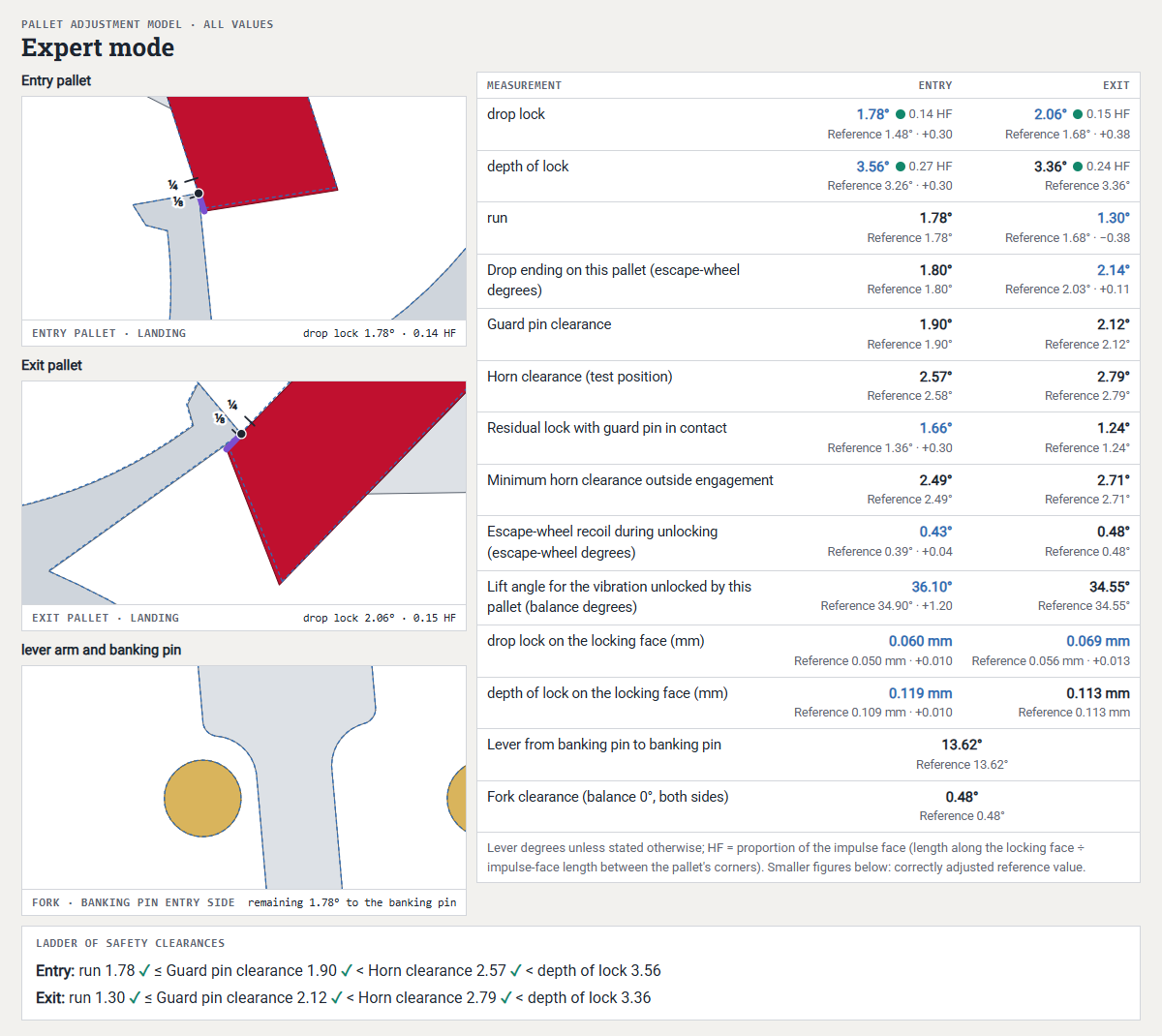 Open animation in a separate window
Pallet adjustment model in expert mode: drop lock, depth of lock, drop, clearances, residual lock, recoil, lift angle and the ladder of safety clearances are updated live.
Fork play at the instant of drop and the pallet-stone rule
Fork play at the instant of drop reveals which pallet you have to move. It is checked as described under Stopping at the instant of drop: drop-lock point, drop, fork play. If it is equal on both sides, the lever swings equally far beyond the centre on each side. Fork play depends on the pallets and not on the banking pins, because the position of the pallets determines where the lever stands at the instant of drop, and the banking pins only act after that. If you pull a pallet out, the lever turns further before the tooth lands. On the adjusted model the fork play is unequal. It is 0.90° for the drop onto the entry pallet and 1.20° for the drop onto the exit pallet, so the difference is 0.30°. At the instant of drop the lever stands 4.9° and 5.2° respectively beyond the centre. Per 0.01 mm, the exit pallet changes the fork play for the drop onto the entry pallet by 0.23 to 0.25°, and the entry pallet changes the fork play for the drop onto the exit pallet by 0.36°. The banking pins do not change it.
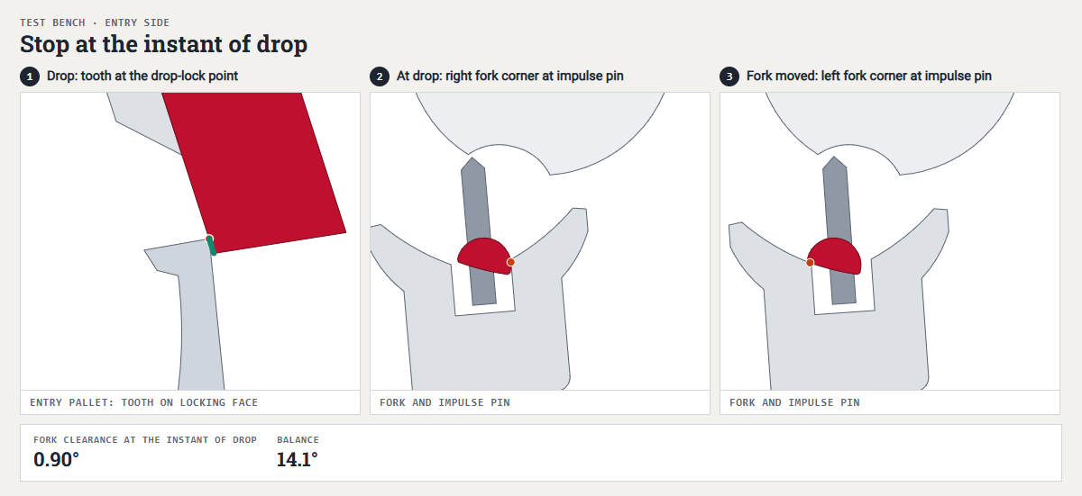 Open animation in a separate window
Stopping at the instant of drop: the tooth drops off, the lever stays put, and the fork can be moved as far as the other fork corner. This travel is the fork play.
Bulova summarises the effect of moving the pallets in a table with eight cases and derives the pallet-stone rule from it:
Finding | Remedy |
|---|---|
lock too light, fork play unequal | pull out the pallet stone opposite the smaller play |
lock too deep, fork play unequal | push in the pallet stone opposite the larger play |
lock too light, fork play equal | both pallet stones out by the same amount |
lock too deep, fork play equal | both pallet stones in by the same amount |
lock correct, fork play unequal | pull out the pallet stone opposite the smaller play and push the one opposite the larger play in by the same amount |
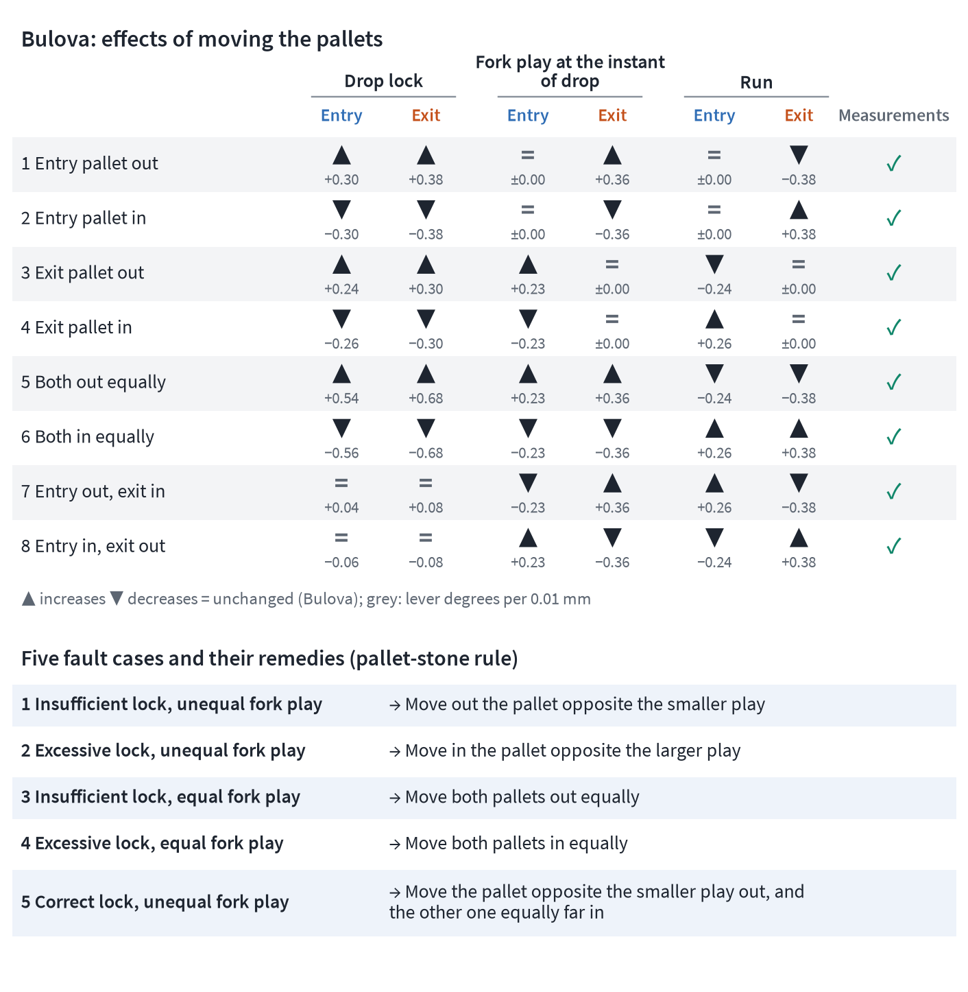
Moving the pallet stones according to Bulova: eight cases as an arrow matrix, with the five fault cases below. In cases 7 and 8 Bulova calls the lock “unchanged”; on the model it changes there by 0.04 to 0.08°.
The rule speaks of the opposite pallet because the run to the banking and the fork play on one side depend on the pallet on the other side. It is the end of impulse at the opposite pallet that determines where the lever stands at the instant of drop. Jendritzki explicitly links the run to the banking to the position of the pallet on the opposite side, and the series of measurements confirms this. On the adjusted model, only the entry pallet changes the run to the banking on exit (0.38° per 0.01 mm), and only the exit pallet changes the run to the banking on entry (0.24 to 0.26°). Accordingly, the technical manual TM 9-1575 advises: if the run to the banking at one pallet is too small, push the opposite pallet in; if it is too large, pull the opposite pallet out.
Smith makes moving the pallets in opposite directions the basic rule. If you move one pallet forward, the other must go back by the same amount. With Bulova this is only the fifth case, in which the lock is already correct and only the symmetry is wrong.
But take care: as a general rule, Smith's statement is misleading. If the lock is too light, it remains just as light after moving the pallets in opposite directions, because the effects of the two pallets on the drop lock almost cancel each other out.
Key point: The run to the banking and the fork play on one side are set at the pallet on the opposite side.
Two schools: the order of checking and adjusting
Where do you start? The first school lets the fork and double roller lead. You first set the banking to suit the fork, impulse pin and double roller, and then set the pallets. This is how the Theorie der Uhrmacherei and Bossart work, and Wilkinson in his notes on resetting the pallets.
The second school lets the escape wheel and pallet fork lead. You first set the locks via the pallets, then the run to the banking via the banking pins, and finally the clearances. Wilkinson's rules expressly require the locks to be corrected first. Our workshop procedure also belongs to this school. First everything is checked, then you set the depth of lock and run to the banking with the pallets, keeping an eye on the drop-lock point. You adjust the banking pins only if the run to the banking remains unequal despite correctly positioned pallets. The solution of the exercise works with the workshop rule and divides the tasks as follows: with the pallets you set the drop-lock point to ⅛ of the impulse face, then with the banking pins the depth of lock to ¼, and with it the run to the banking. With fixed banking, only the pallets remain for this as well. The guard pin comes last.
Source | first | then | last |
|---|---|---|---|
Theorie der Uhrmacherei | horn clearance via the banking pins | guard pin, lock via the pallets | run to the banking via the banking pins |
Bossart | banking pins according to the locking angle | pallets, horns | guard pin |
Wilkinson, notes | banking according to guard pin or fork corner | set the pallets for the drop | give run to the banking, adjust guard pin |
Wilkinson, rules | locks via the pallets | banking | clearances |
our workshop procedure | check everything, then pallets for depth of lock and run to the banking | banking pins only if the run to the banking is unequal | guard pin |
this article, solution of the exercise | check everything, then the drop-lock point (⅛) with the pallets | depth of lock (¼) and run to the banking with the banking pins; with fixed banking, again with the pallets | guard pin |
Almost everywhere the guard pin comes at the end, explicitly so in Helwig. If you adjust it earlier, as the Theorie der Uhrmacherei does, you have to check it again after every move of the pallets. This is because the pallets change the depth of lock but not the guard pin clearance, and so every move also changes the lock that still remains with the guard pin in contact. With fixed banking, which is the norm today, only the first route remains anyway, because the banking cannot be adjusted and therefore dictates everything else. We recommend the second route with the guard pin last, as in the solution of the exercise.
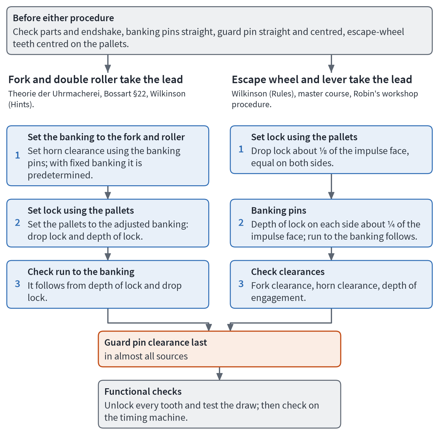
Both schools end with guard pin clearance, function tests and the timing machine.
Exam cases on the simulator
Exam questions on the escapement almost always follow the same pattern of finding, reasoning and adjustment. In the reasoning, you ask the two questions of the core rule: where does the tooth land, and where does the lever come to rest? In the pallet adjustment model's “exam case” mode, you can load the cases and compare the state before and after the adjustment.
Finding | Reasoning | Adjustment | Result on the model |
|---|---|---|---|
Lock too small, run to the banking on exit too large (master-course questions 1994) | Only the entry pallet changes the run to the banking on exit | entry pallet out | Entry pallet 0.01 mm too far in: drop lock 1.46°/1.64°, run to the banking 1.22°/0.70°. After 0.01 mm out: 1.76°/2.00° and 1.22°/0.34° |
On entry, run to the banking, guard pin clearance and horn clearance too large (journeyman's examination) | All three values on one side too large: the cause is the banking pin on that side | banking pin on entry narrower | Run to the banking, guard pin clearance, horn clearance and depth of lock on entry become smaller; the drop lock stays the same (1.48°/1.68°). Banking pin on entry 0.25° too wide: run to the banking 2.02°, guard pin clearance 2.14°, horn clearance 2.82°, depth of lock 3.50°. After 0.25° narrower: 1.78°, 1.90°, 2.58° and 3.26°; the exit stays the same. |
Guard pin clearance and run to the banking too large on both sides (journeyman's examination) | equal on both sides: both banking pins; only guard pin clearance wrong: guard pin | both banking pins narrower | both banking pins 0.25° too wide: guard pin clearance 2.14°/2.36°, run to the banking 2.02°/1.92°, depth of lock 3.50°/3.60°. After 0.25° narrower: 1.90°/2.12°, 1.78°/1.68° and 3.26°/3.36°; the drop lock stays at 1.48°/1.68°. |
Lock larger on entry than on exit (journeyman's examination, Chamber of Crafts) | Is it the depth of lock or the drop lock that differs? | run to the banking unequal: opposite pallet or banking pin; drop lock unequal: pallet shape | before adjustment: depth of lock 2.98°/2.34°, drop lock 1.76°/2.00°. The difference lies in the run to the banking |
Banking pin on entry outwards: does draw become stronger? (Chamber of Crafts) | Separate depth of lock and effective draw | – | Depth of lock and safety increase, the effective draw angle on entry decreases |
The Pforzheim question set tests the core rule in words. If you set the entry pallet deeper, the run to the banking on the opposite side shrinks, on the model by 0.20° per 0.005 mm. If you set the exit pallet shallower, the “Gang”, here meaning the drop lock, becomes shallower on both sides, and the run to the banking on entry increases by 0.26° per 0.01 mm. Bulova's five fault cases (pallet-stone rule) are equally suitable as an exercise.
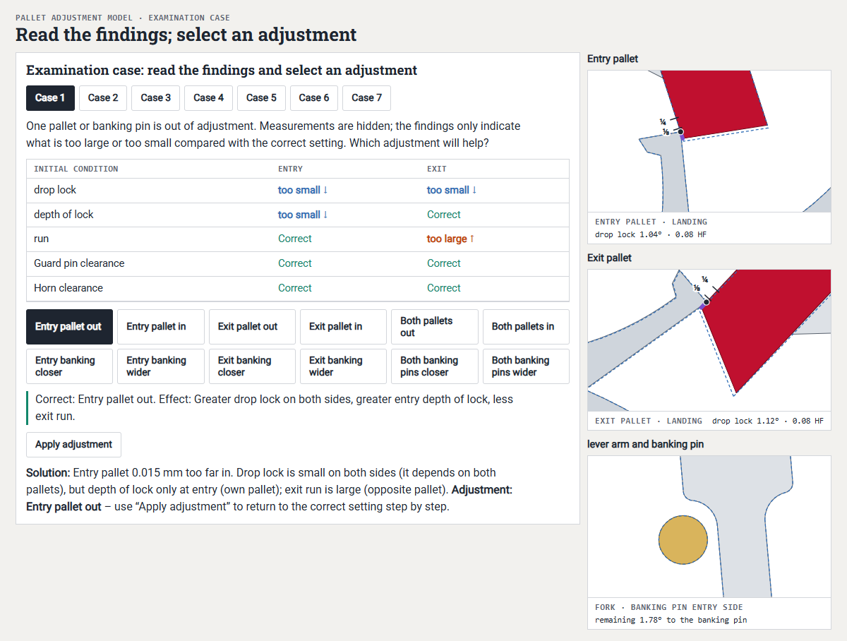 Open animation in a separate window
In “exam case” mode you load a finding, choose an adjustment and compare the result with the ghost image.
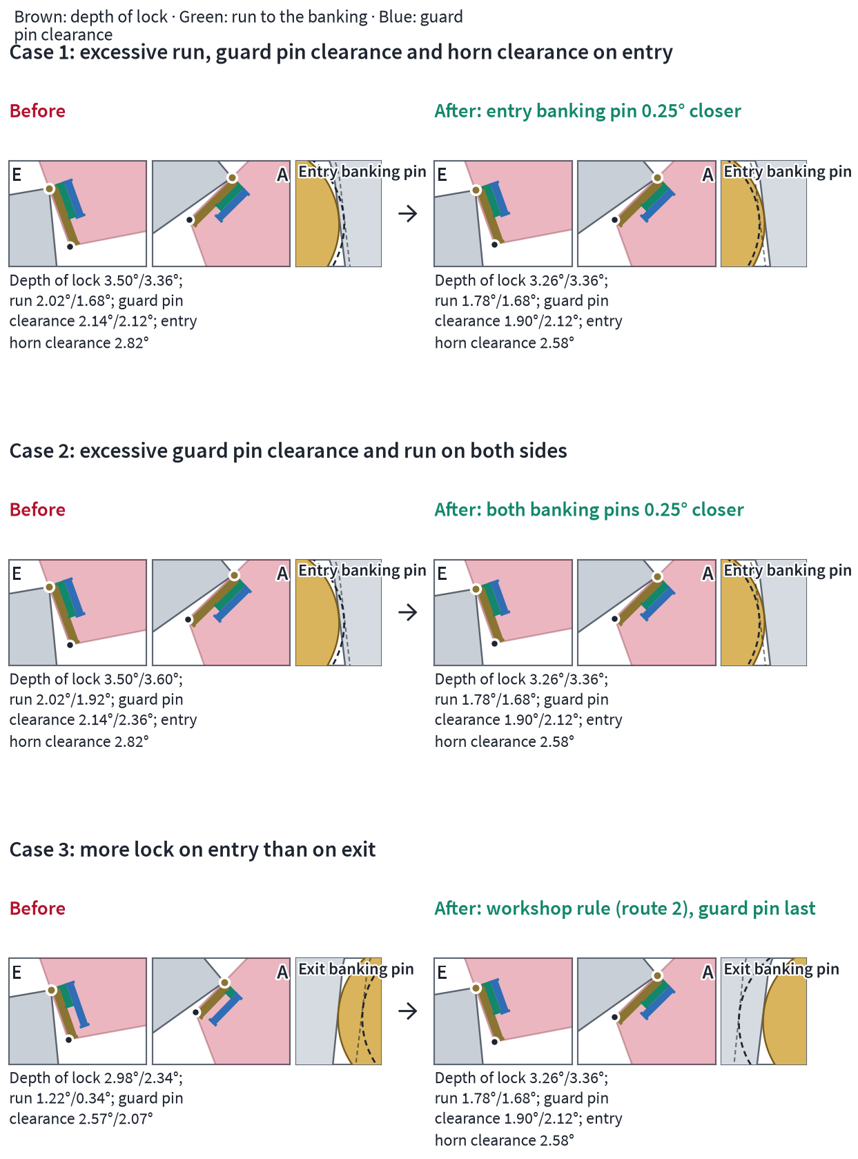
Exam cases before and after.
1. On the exercise: what changes in the solution if the banking is fixed, and what if only the banking pins are adjustable?
With fixed banking, only the pallets remain. The run to the banking on exit, which is too small, is then increased by pushing the entry pallet in. With 0.02 mm the run to the banking becomes almost symmetrical (1.22°/1.08°), but the lock is shallower than the workshop rule requires, and the guard pin clearance (2.57°) exceeds the depth of lock on entry (2.38°). The guard pin must therefore be moved forward, because otherwise a tooth could land on the impulse face with the guard pin in contact. If only the banking pins are adjustable, you open the banking pin on exit by just under 0.9°. Depth of lock and guard pin clearance on exit increase with it, and the drop lock stays the same. The workshop rule needs both, pallets and banking pins, and the guard pin comes last.
2. Final examination, ECH-133: is the horn clearance larger than, smaller than or equal to the guard pin clearance?
At the outer horn, the horn clearance is larger. If a shock hits the watch just before the impulse pin swings into the fork, the guard pin is still in contact with the safety roller, and the lever has moved aside by the guard pin clearance. If the horn clearance were smaller there, the impulse pin would strike the horn. At the inner corner of the horn, according to Bossart, it may be about equal to or slightly smaller than the guard pin clearance. On the model, the horn clearance is greater than the guard pin clearance along the whole horn (The ladder of safety clearances and the rebanking limit).
Timing machine and lift angle in formulas
In the workshop part we interpreted the timing machine's display (Measure first: the escapement on the timing machine). Here we turn to the formulas behind it. We show how the device estimates the amplitude from a measured time, how accurately the 180° method gives the lift angle and why the lift angle on the timing machine does not correspond exactly to the engagement on the model. Finally, we convert beat error from milliseconds into degrees. The formula symbols are listed in the table under Parameters and formula symbols.
Amplitude from the lift time
The timing machine does not measure an angle, but the time from the unlocking sound to the drop sound of the same beat. During this time, the balance passes through the lift angle. If the device knows the lift angle and the frequency, it can calculate the amplitude from them.
The timing-machine manufacturer Witschi gives the formula itself. In words: the amplitude is the lift angle divided by twice the sine of π times frequency times time. For the workshop you can leave out the sine, because the angle π · f · t is small, and for small angles the sine is almost equal to the angle itself, measured in radians.
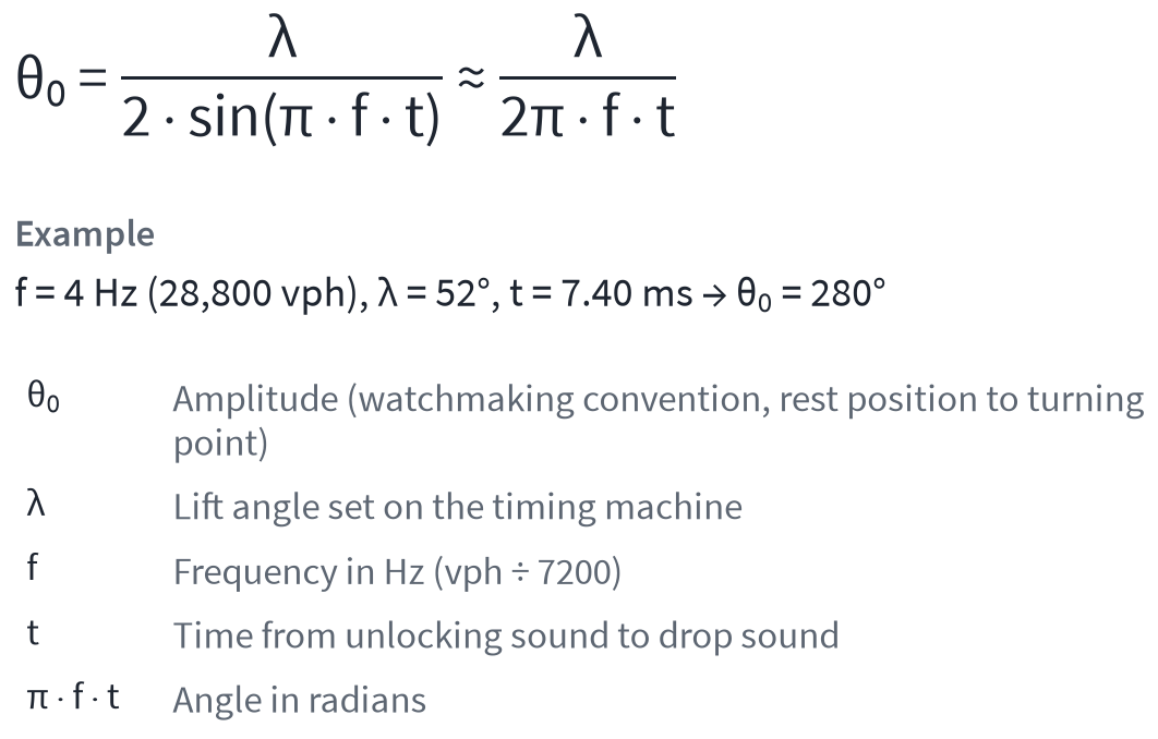
Amplitude from the lift time. θ₀ amplitude, λ lift angle, f frequency in Hz, t time from the unlocking sound to the drop sound. Source: Witschi, Prüfmethoden mechanischer Uhren (2025).
Behind this lies a sinusoidal oscillation θ = θ₀ · sin(2π · f · t). Unlocking lies at −λ/2 and drop at +λ/2, that is, symmetrically about the dead point. If you calculate the time between the two points and rearrange the equation for θ₀, you get the formula. The approximation without the sine gives only 0.6° too little at 180° and only 0.4° too little at 280°.
Witschi names four assumptions for this. First, the balance moves along a sine curve, which only holds as long as the escapement influences it little. Second, the dead point lies midway between unlocking and drop. Third, the measured time corresponds approximately to the lift time, but deviates from it somewhat because of the run to the banking. Fourth, the lift angle entered is correct. How much it matters if one of these assumptions does not quite hold is explained in The lift angle in more detail.
Frequency, lift angle | 180° | 200° | 250° | 280° | 300° |
|---|---|---|---|---|---|
4 Hz, 44° | 9.75 | 8.77 | 7.01 | 6.26 | 5.84 |
4 Hz, 49° | 10.87 | 9.77 | 7.81 | 6.97 | 6.51 |
4 Hz, 50° | 11.09 | 9.97 | 7.97 | 7.11 | 6.64 |
4 Hz, 52° | 11.53 | 10.37 | 8.29 | 7.40 | 6.91 |
4 Hz, 54° | 11.98 | 10.78 | 8.61 | 7.69 | 7.17 |
2.5 Hz, 35° (our model) | 12.40 | 11.16 | 8.92 | 7.96 | 7.43 |
2.5 Hz, 44° | 15.60 | 14.03 | 11.22 | 10.01 | 9.35 |
You should know how sensitively the reading responds. The displayed amplitude is proportional to the lift angle entered. If, on a movement with 52°, you enter a lift angle that is 1° too large or too small, a reading of 280° shifts by around 5.4°. A measurement error of 0.1 ms shifts the reading at 4 Hz, 52° and 280° by around 3.8°, and on our model by around 3.5°. Beat error, by contrast, has practically no effect on the amplitude, because it shifts impulse only slightly relative to the dead point. There the balance is at its fastest and its speed hardly changes, so it needs almost the same time for the lift angle.
This proportionality gives the examples 237°, 297° and 331° under What the timing machine measures and Determining a movement's lift angle. Two further examples apply to a true 280°. On an ETA 2824-2 with 50°, the timing machine set to the 53° of the Witschi table likewise shows 297°. And on a movement with 35° like our model, a timing machine set to 44° shows 352° and falsely suggests a risk of rebanking.
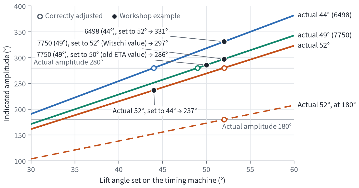
Displayed amplitude plotted against the set lift angle, with the workshop examples.
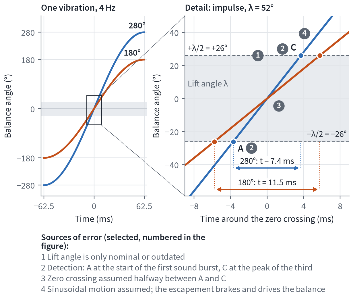
The smaller the amplitude, the longer the balance takes for the same lift angle.
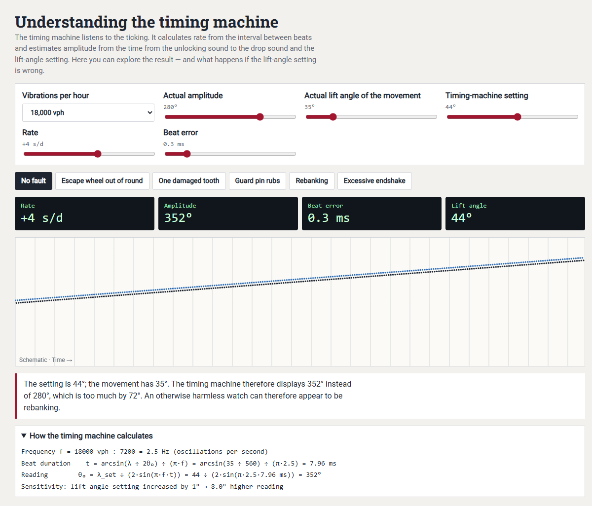 Open animation in a separate window
The timing machine simulator in formula mode, with which you can recalculate the values yourself.
Incidentally, older timing machines did not do the calculation themselves. In 1967 Weger describes how to determine the amplitude by hand. At low gain, the timing machine records only the loudest sound, the drop. If you turn up the gain, it also picks up the unlocking, and the row of dots jumps sideways by the time in between, around 10 ms in Weger's case. You convert the size of the jump on the strip into milliseconds and, using the beat rate and lift angle, read off the amplitude from a nomogram or a measuring disc.
As a rule of thumb, you can remember that with a lift angle of around 50°, every degree by which the entered lift angle deviates shifts the displayed amplitude by around 2%. A measurement error of 0.1 ms shifts it by around 4° at 4 Hz.
The 180° method calculated
The same formula can be used to recalculate the 180° method from Determining a movement's lift angle. At a true 180°, the sine in the formula is exactly λ/360°. If, in this state of wind, you adjust the lift angle on the timing machine until it shows 180°, you are therefore setting a lift angle of 360° times the sine of π times frequency times the time measured at 180°.
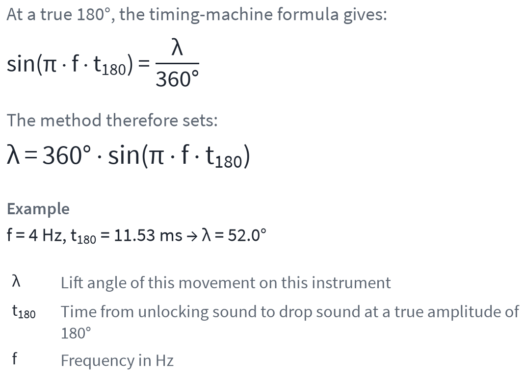
Lift angle from the 180° method. t₁₈₀ is the time the timing machine measures at a true 180°.
The reading is therefore exactly right at 180°, whatever small deviations there are in the movement and the device. What remains open is how accurately the eye hits the 180° and what happens at larger amplitudes.
Let us look at the eye first. If, during calibration, the balance actually swings with the amplitude θab, that is, slightly off 180°, the lift angle found is out by the factor 180°/θab. In words: the value found is the true lift angle times 180°, divided by the amplitude during calibration. All later readings shift by the same factor.
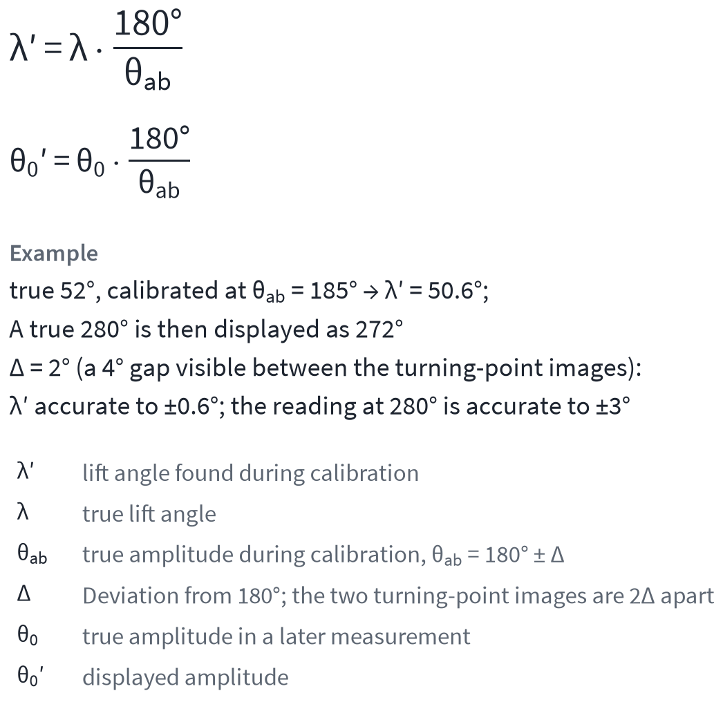
Calibration at θab instead of 180°: λ′ is the lift angle found, λ the true lift angle; θ0′ is the amplitude displayed afterwards, θ0 the true amplitude.
Amplitude during calibration | found at a true 52° | found at a true 44° | reading at a true 280° |
|---|---|---|---|
175° | 53.5° | 45.3° | 288° |
180° | 52.0° | 44.0° | 280° |
185° | 50.6° | 42.8° | 272° |
190° | 49.3° | 41.7° | 265° |
During calibration the eye sees double the error, because at 180° plus Δ the two turning-point images are 2Δ apart. If you can just make out a gap of 4° (Δ = 2°), you are within about ±0.6° for the lift angle and within about ±3° at 280°.
What about large amplitudes? Let us assume, in a simplified example, that the dynamics or the sound detection shift the measured time at 4 Hz and a true lift angle of 52° by a fixed amount Δt.
fixed time offset Δt | lift angle after calibration at 180° | reading at a true 280° | reading with a fixed setting of 52° |
|---|---|---|---|
0.1 ms | 52.45° | 278.7° | 276.3° |
0.2 ms | 52.9° | 277.3° | 272.7° |
0.3 ms | 53.3° | 276.1° | 269.1° |
Calibration at 180° compensates for a large part of this, but not all of it. At 280°, a good third of the error that you would have with the fixed nominal value remains. No source documents how large Δt really is, so the figures only show the direction.
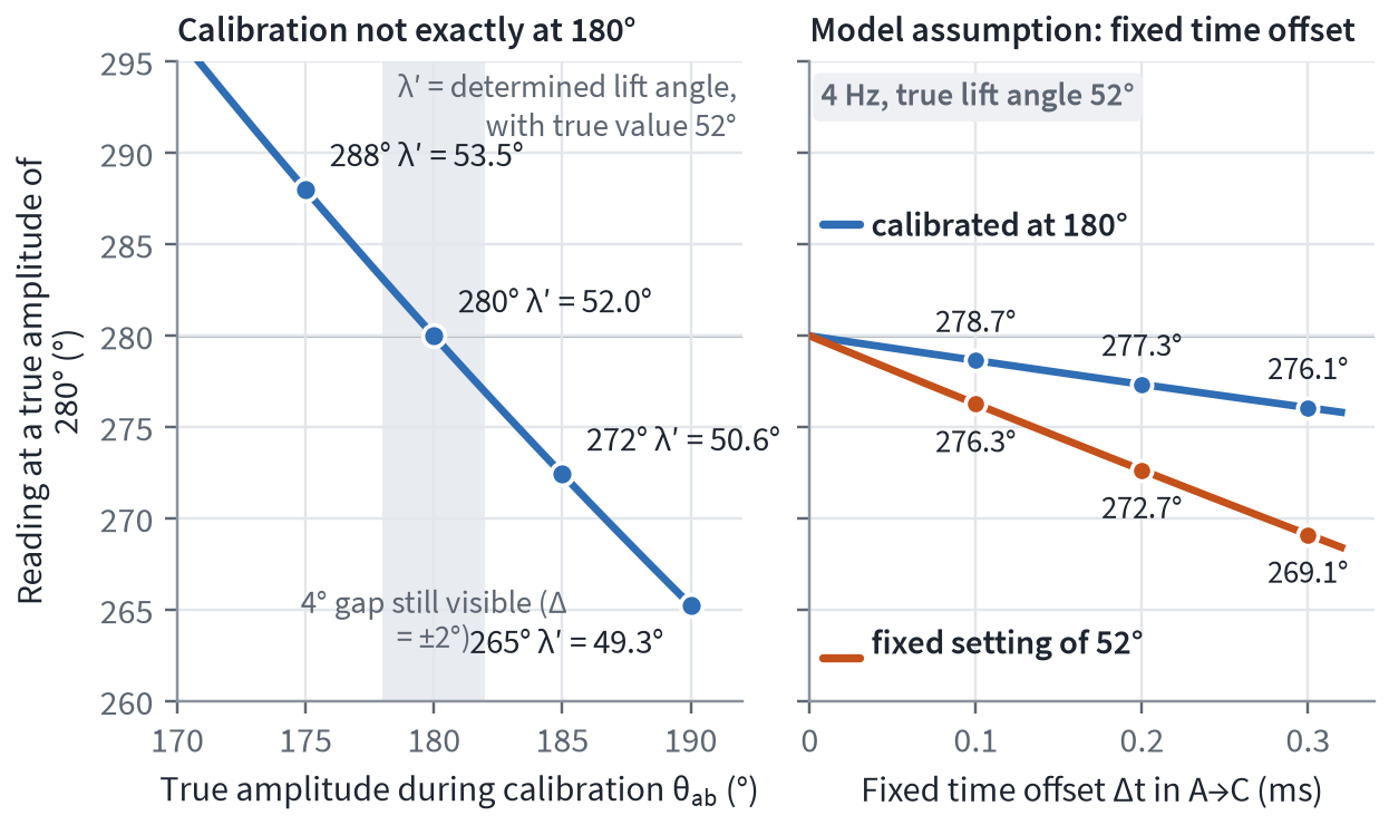
Error propagation in the 180° method: reading error during calibration and fixed time offset (model assumption).
The value found in this way is the lift angle of this movement on this device, because it matches movement and timing machine to each other. It may therefore differ from the manufacturer's value. A manufacturer, too, specifies different values for the same movement depending on the type of timing machine, although this example comes from a different type of escapement.
Key point: The 180° method matches the timing machine to the movement. The reading is then exactly right at 180° and accurate to within a few degrees at 280°.
The lift angle in more detail: what the model shows and what the timing machine hears
Why does the lift angle you enter on the timing machine not match exactly the range in which the impulse pin and fork touch each other? There is only one lift angle, but in the model, in the running movement and on the timing machine it shows up slightly differently in each case. We will look at these differences one by one.
What the model shows. Our model determines the position of the components from their contacts, but quasi-statically, that is, without inertia. The table shows the events of a vibration in both directions.
Event | exit unlocks | entry unlocks |
|---|---|---|
impulse pin touches the fork | −20.35° | +19.75° |
end of unlocking | −9.95° | +9.55° |
change from pallet lift to tooth lift | +8.0° | −5.6° |
drop | +14.2° | −15.15° |
impulse pin free, lever at the banking pin | +19.85° | −20.40° |
lift angle (contact to drop) | 34.55° | 34.9° |
centre of the range | −3.1° | +2.3° |
From the impulse pin's first contact with the fork to the drop, the balance turns through 34.55° (exit unlocks) and 34.9° (entry unlocks) respectively, that is, around 35°. Of this, 10.4° and 10.2° respectively are accounted for by unlocking, 17.95° and 15.15° by pallet lift, and 6.2° and 9.55° by tooth lift.
The range is not centred on the dead point. Its centre lies 2 to 3° towards the side from which unlocking comes. The timing machine, by contrast, assumes that unlocking and drop lie symmetrically at ±λ/2. This does not produce a gross error, because an eccentricity e enters the time only quadratically. The measured time is made up of the path to the left and the path to the right of the dead point. If the engagement is off-centre, one path becomes longer by e and the other shorter by e. Because the balance moves equally fast at both ends of the symmetrical range, the two changes in time cancel each other out except for a small remainder. A fixed time offset Δt may come on top of this. On the model, the eccentricity changes the reading at 280° by less than 0.02°.
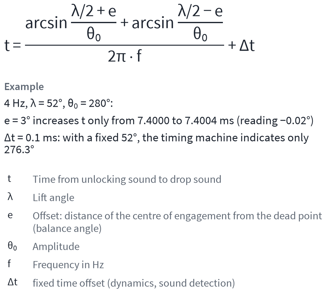
Time from the unlocking sound to the drop sound with off-centre engagement (eccentricity e) and fixed time offset Δt.
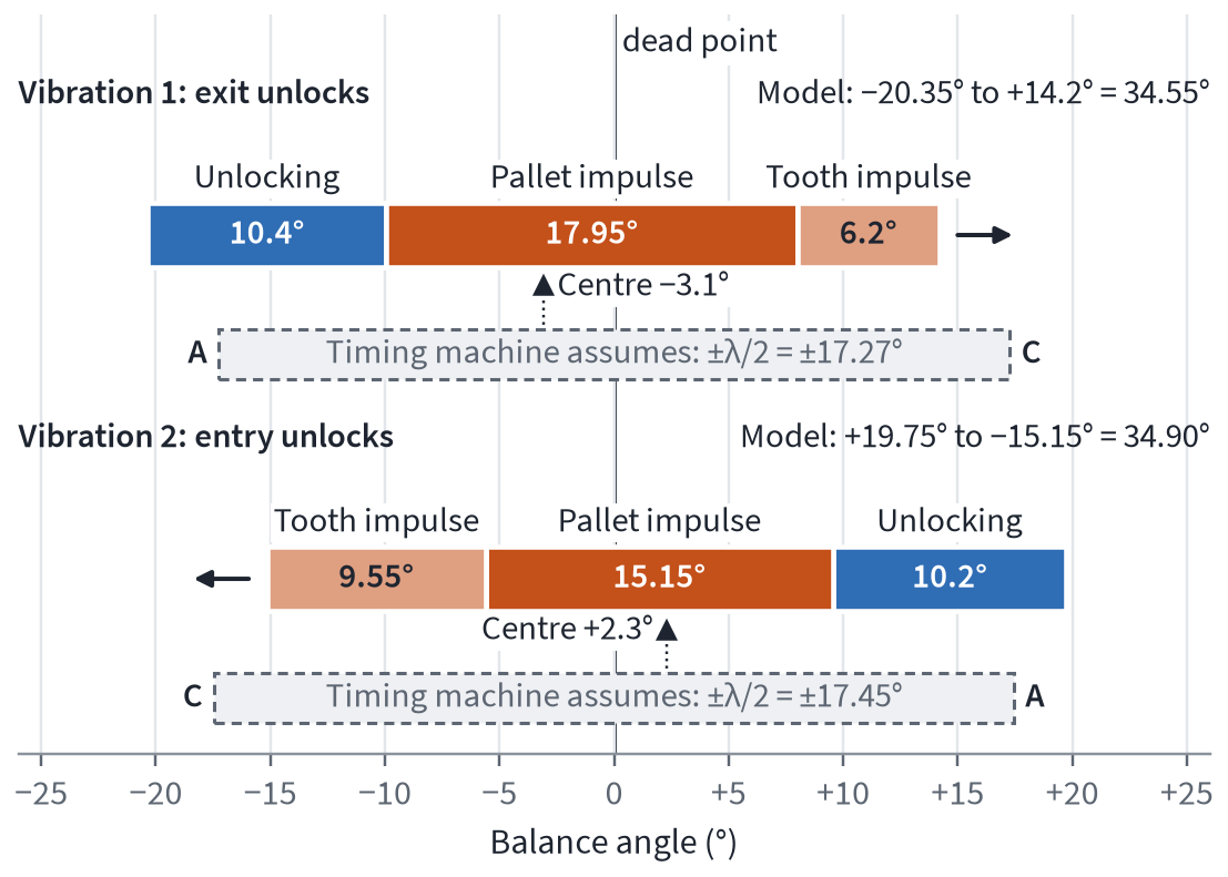
Engagement range on the model compared with the timing machine's assumption. The centre lies 3.1° and 2.3° respectively towards the side of unlocking.
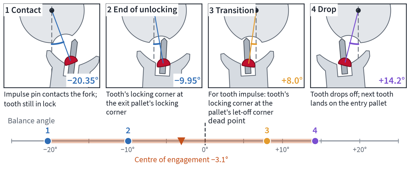
Fork and impulse pin at the four events of a vibration.
The end of the engagement is striking. In the model the fork stays on the impulse pin after the drop and pushes it through the run to the banking. The impulse pin is only released at +19.85° and −20.40° respectively, that is 5.65° and 5.25° after the drop, and precisely at the instant at which the lever reaches the banking pin. This follows from the geometry and not from the lack of inertia. What the literature says about this is given further below under “Lead and lag of the fork”.
What the timing machine hears. The measurement runs from the start of the first to the peak of the third sound burst (What you hear). The first burst belongs to the impulse pin striking the fork, the third to the drop and to the lever striking the banking pin, the banking-pin impact. Between the drop and the banking-pin impact lies the run to the banking. On our model it is 1.78° on entry and 1.68° on exit, measured at the lever. Witschi names precisely this run to the banking as the reason why the measured time does not quite correspond to the lift time.
In addition, the timing machine assumes a sinusoidal oscillation. During the engagement, unlocking first brakes the balance, and then impulse drives it. In the very range whose time the timing machine measures, the balance therefore does not move like the free oscillation that the formula assumes.
Clearances and tolerances. Because of fork clearance, the impulse pin meets the fork slightly later than the shape without play would lead you to expect. On our model, fork clearance is 0.48° at the lever, and this delay is already included in the contact at −20.35° and +19.75° respectively. If fork clearance, horn clearance or banking change in the movement, the unlocking sound shifts too. Pivot play of the lever and balance shifts the centreline, and differently in the vertical positions than lying flat (Weger). Manufacturing also varies: on a Unitas/ETA 6498 with an impulse-pin radius of 1.15 mm and a centre distance of 4.95 mm between lever and balance, an impulse-pin radius that differs by 0.01 mm changes the lift angle by around 0.5°. At 280°, that is around 3° on the display.
Lead and lag of the fork. During unlocking the fork lags behind the impulse pin, because first the fork clearance has to be overcome, and then the inert lever has to get moving. After the drop it runs ahead of it; this is how Helwig and Röseler describe it. Draw pulls the lever to the banking pin, the fork separates from the impulse pin before the run to the banking ends, and the lever rebounds off the banking pin. What else the high-speed recordings show is given under What really happens.
If this is correct, the impulse pin's impact begins slightly later, and the effective impulse ends earlier, than the model shows. The sounds, however, do not mark these limits precisely. In the model, the drop and the banking-pin impact are 5.65° and 5.25° of balance angle apart respectively; at 280° and 2.5 Hz that is around 1.3 and 1.2 ms. If the same amount of time lay between them on the movement, the display would jump by around 40°, depending on which of the two impacts the timing machine takes as the drop sound, since even 0.1 ms makes around 3.5° (Amplitude from the lift time). According to Helwig and Theorie der Uhrmacherei, by contrast, the drop and the banking-pin impact sound like a single impact (What you hear, What really happens).
Whether draw could snatch the lever ahead can be estimated. This is a rough estimate by hand and not a result of the simulator. The angular acceleration α is the draw torque divided by the moment of inertia of the lever, fork and guard pin. With uniform acceleration, the lever needs the time t = √(2φ/α) for the run to the banking φ. The draw torque at the lever is around 0.1 to 0.15 µN·m (coefficient of friction 0.05), calculated from an assumed escape-wheel torque of 1.2 µN·m ± 50%. Depending on the side and the friction, it lies between 0.01 and 0.27 µN·m. According to the 3D model, the lever has a moment of inertia of around 0.28 mg·cm² (2.78 · 10⁻¹¹ kg·m²; lever with fork, guard pin, pallet stones and staff, 10.2 mg in total). Starting from rest, it therefore needs around 3.4 to 4.2 ms for the run to the banking, 2.5 to 11 ms depending on the assumptions. The balance, by contrast, covers the corresponding distance in around 1.2 to 1.3 ms. Draw alone therefore does not snatch the fork ahead.
In our model the fork cannot run ahead at all, because in the run to the banking, as before during impulse, it continues to rest against the impulse pin and pushes it until the lever rests against the banking pin. To be faster, the lever would have to push the balance along with it, which, converted to the fork, is roughly several hundred times more inert. In the rigid model, the interval between the drop and the banking-pin impact therefore results from the geometry. This does not contradict the observations of Helwig and Röseler, because things are wilder in the watch than in a rigid model. High-speed recordings show, for example, that after the drop the tooth bounces about twice on the locking face before it comes to rest. Elastic deformation of the components, bouncing and oil are not included in our estimate.
Pallet fork and escape wheel over time: motion in the model and the dynamic course as described in the literature.
Sound detection. A beat sound is not a sharp crack; it swells and dies away again. Which point counts as the start and which as the peak depends on threshold, gain and signal shape. Weger and Reuer already described how the instrument picks up different impacts depending on the control setting. The display averages over at least 16 beats, and an offset of 0.1 ms changes it by around 3.5 to 3.8°.
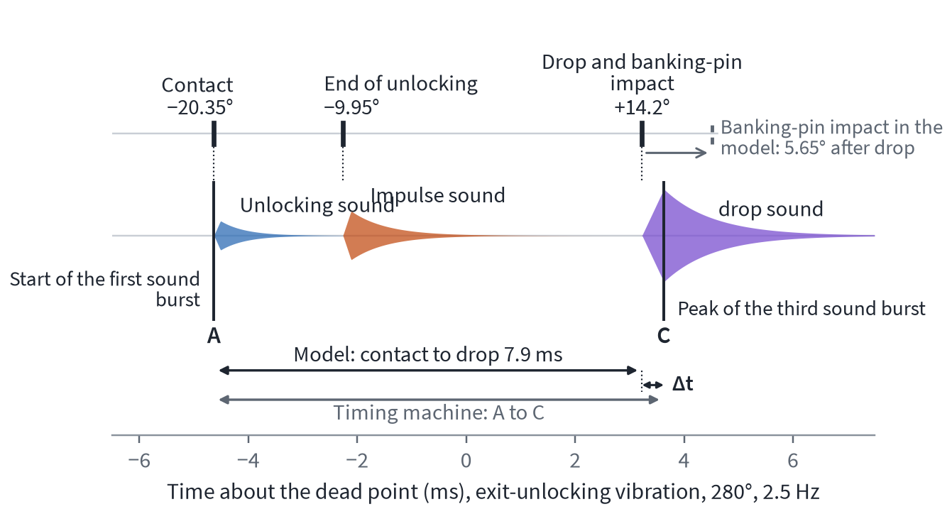
Contacts on the model compared with the timing machine's measuring marks. The banking-pin impact is drawn at the position of the drop.
The 180° method as a bridge. It determines the value with which the timing machine calculates correctly for the movement in question. Fixed offsets from clearances, dynamics and sound detection are then already included in the lift angle that has been set. At 180° the display is then exactly right; at 280° a small residual error remains (The 180° method calculated).
For the workshop this means: take the manufacturer's value as the starting value. If there are doubts, for example because the timing machine shows rebanking or an implausibly low amplitude despite a normal mainspring, determine the lift angle with the 180° method. If you want to compare values from the same movement, always measure with the same instrument and the same setting.
Key point: There is only one lift angle, but it shows itself slightly differently in the model, in the running movement and on the timing machine. The 180° method calibrates the timing machine to the movement in question.
Beat error in milliseconds and in degrees
A beat error shows on the timing machine as unequal intervals between beats. What is displayed is half the difference between two successive intervals t₁ and t₂.
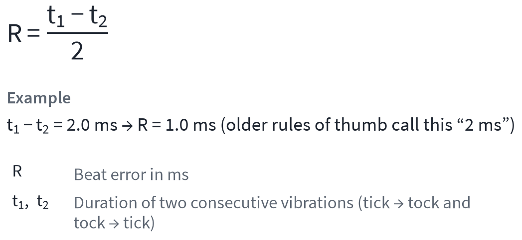
Beat error R in milliseconds from two successive beat intervals.
You obtain the beat error in degrees by multiplying R by π, the frequency and the amplitude. R is entered in seconds and the amplitude in degrees.
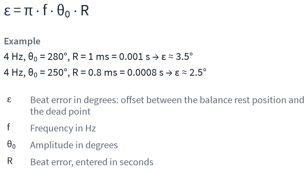
Beat error in degrees: ε is the beat error in degrees, R the beat error in seconds. Example: 4 Hz, 280°, 1 ms ≈ 3.5°.
At 4 Hz and 280°, 1 ms therefore corresponds to around 3.5°, and 0.8 ms at 250° is around 2.5°. It follows that the same angular error gives more milliseconds at low amplitude, because the balance then passes through the dead point more slowly.
But take care: older rules of thumb are often calculated differently. For 18,000 vph and an impulse pin turned by 2°, Weger gives half-oscillations of 201 and 199 ms, that is, a difference of 2 ms. That is the whole difference t₁ − t₂ without the factor ½. Calculated as beat error R, it is 1 ms, and at 2.5 Hz that fits an amplitude of a little over 250°.
Exam question: Does the distance between the two rows of dots become larger or smaller at higher amplitude?
Smaller. At high amplitude the balance passes through the dead point faster, so for the same angular error the time difference shrinks in proportion to the amplitudes. 2° of beat error is around 0.72 ms at 4 Hz and 220°, and around 0.53 ms at 300°.
Escapement and rate
The escapement is meant to drive the balance without disturbing its timekeeping, but no escapement entirely succeeds in this. Yet why does a lever watch lose in the vertical positions? That depends on where in the arc of oscillation the escapement brakes the balance and where it drives it.
Before or after the dead point
The explanation comes from a rule that in the technical literature is usually named after the astronomer George Biddell Airy. The WOSTEP Feinregulierung course notes summarise it, without the name, in a table with four fields. Whether an intervention shortens or lengthens the oscillation depends on whether it accelerates or brakes the balance and whether this happens before or after the dead point.
before the dead point | after the dead point | |
|---|---|---|
Acceleration | Gaining | Losing |
Deceleration | Losing | Gaining |
The reasoning is easy to picture. If the balance is accelerated before the dead point, it reaches it earlier, and the watch gains. If it is only driven after the dead point, it swings out further and needs more time for the longer path, so the watch loses. With braking it is the other way round. If the escapement brakes the balance before the dead point, it arrives there later, and the watch loses. If it is braked after it, the remaining arc becomes shorter, and the watch gains.
How strongly an intervention affects the rate does not depend on its size alone. The effect grows with the distance from the dead point, is zero at the dead point itself, and also grows at lower amplitude and at lower frequency. From this Bossart concludes for designers that a balance with a large moment of inertia and a large amplitude are favourable. Ideal would be a short impulse exactly at the dead point (Reuer, Berner), but no escapement achieves this, because it must unlock first.

Try out the position of the impulse: where the impulse meets the balance decides between gaining and losing, and the amplitude decides the strength of the effect.
Key point: Driving before the dead point makes the watch gain, driving after it makes it lose. With braking it is the other way round.
Why the Swiss lever escapement makes a watch lose
Let us apply the rule to the Swiss lever escapement. A half-oscillation has three sections that affect the rate. First comes unlocking, in which the impulse pin has to release the lever against draw. This brakes the balance before the dead point and makes the watch lose. Still before the dead point comes the first part of the impulse, which makes the watch gain, and after the dead point the second part of the impulse makes it lose again. Two of the three sections therefore make the watch lose, and because unlocking takes up part of the path before the dead point, less path remains for the impulse before it. That is why losing always predominates.
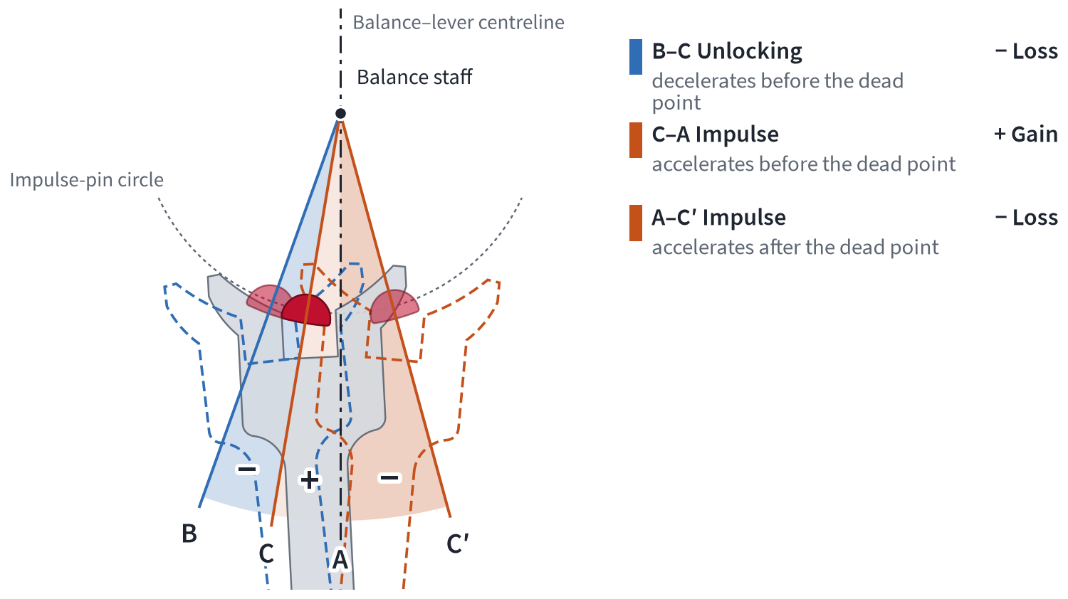
Where the escapement influences the rate: unlocking and the impulse after the dead point cause losing, the impulse before it causes gaining. Shown is the half-oscillation in which the entry side unlocks. B lies 19.75° and C 9.55° before the dead point A, C′ lies 15.15° after it.
Bossart works this through with round figures. He assumes a lift angle of 30°, of which 6° is unlocking. Of the impulse, 9° lies before the dead point and 15° after it. The 9° before cancel out 9° of the impulse after. What remains is 6° of impulse after the dead point and 6° of unlocking, together 12° with a losing effect. With 1°30′ instead of 2° of lock at the lever, unlocking at the balance falls to 4°30′ and the losing effect to 9°.
On our model, unlocking lies entirely before the dead point. In the half-oscillation shown in the figure, the entry side unlocks. Unlocking extends from 19.75° to 9.55° before the dead point, and the tooth drops 15.15° after it. According to Bossart's simple angle balance, this leaves 10.2° of unlocking plus 5.6° of impulse after the dead point, together around 15.8° with a losing effect. In the opposite direction, unlocking extends from 20.35° to 9.95° before the dead point, and the drop lies 14.2° after it. There it is 10.4° plus 4.25°, so around 14.7°. This is more than in Bossart's example, because the workshop rule with ¼ of the impulse face brings a deeper lock and therefore a longer unlocking.
Losing increases as the amplitude falls, because the same intervention then takes up a larger part of the arc of oscillation. In the vertical positions, pivot friction according to Berner is about three times as great, and the amplitude falls by 40 to 60°. That is why a lever watch loses more in the vertical positions than lying flat. Some watchmakers counter this with a very flat rounding of the balance pivot end, to increase friction in the horizontal positions. Daniels even suggests an off-centre hollow in the cap jewel, so that the balance pivot no longer runs on its tip at all.
For the rate, a small lift angle, little lock, small draw, a small run to the banking, light components and a large amplitude would be best (Bossart). This describes the influence on the rate and is not an adjustment rule. The workshop rule ⅛/¼ deliberately accepts the somewhat greater losing, because in return it offers more safety (for the point of contention, see What really happens). A constant losing rate can in any case be regulated out. Only the part that changes with amplitude can cause trouble.
For master watchmakers and designers, a formula given by Glaser in 1966 in DIE UHR is of interest. It describes the rate error caused by the impulse in closed form and, simplified, reads g = −(1/a₀) · [K + K′ · c₁/a₀]. Here a₀ is the amplitude in radians, K and K′ are two characteristic values of the escapement, and c₁ stands for the decrease in amplitude due to bearing friction. For a gent's wristwatch, Glaser gives K = 52 s/d and K′ = 2700 s/d, plus c₁ = 0.01 with the balance staff vertical (lying flat) and 0.04 with it horizontal (hanging). Recalculated, this gives around −12 s/d at 270° and −19 s/d at 180° lying flat, and around −16 and −27 s/d hanging. The master-course notes summarise the remedies in three points: keep the impulse short, place it as close as possible to the dead point, and ensure a large amplitude.
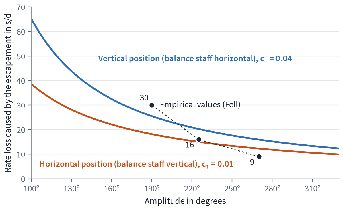
Losing caused by the escapement against amplitude according to Glaser's formula, for a watch lying flat and hanging.
Key point: The Swiss lever escapement always makes the watch lose a little, and all the more so the lower the amplitude.
Compensation in the oscillating system
Incidentally, the oscillating system itself also influences the rate via the amplitude, for example through the way the hairspring is attached, the hairspring's centre of gravity and a poise error of the balance, whose effect reverses at about 220° (Bossart, Reuer, Berner). The poise of the balance is therefore checked at 160 to 180°, because around this reversal point it hardly affects the rate and does not show up there. In the workshop, losing at low amplitude is usual. Gaining is nevertheless possible if such additional effects predominate, for example if the hairspring rests against one side of the regulator pins. How differently this can turn out is shown by Eisenegger's run-down diagram (What the timing machine measures), measured on three movements of the same calibre over the entire power reserve. As the amplitude falls, the rate of two movements rises by around 5 and 10 s/d respectively; in the third it falls as soon as the amplitude drops below about 200°. That is material for an article of its own.
Origins and relatives
The Swiss lever escapement did not come into being in a day, and it has relatives that solve some things differently. The first section is an excursus for everyone; the rest is master-level material.
Excursus for everyone
A short history
The Swiss lever escapement has no single inventor. It grew in steps, in England and on the Continent at the same time.
Thomas Mudge built the first detached lever in London in the 1750s. His watch for Queen Charlotte of 1769/70 survives. Mudge's escape wheel had 20 teeth, and draw was still missing.
Draw is found around 1805 in Lallemand in a French pocket watch, in 1812 in Breguet on a straight-line lever with a counterweight, and around 1819 in Massey in England. In Switzerland, Georges-Auguste Leschot established it around 1825. From about 1825 there were series-produced levers, with club teeth in Switzerland and France and with pointed teeth in England. Around 1850 the straight-line lever with counterweight and the double roller came together. Stolberg dates the Swiss club-tooth lever escapement from 1855.
It became established between 1850 and 1900. In 1866 Moritz Großmann won the British Horological Institute's competition with his prize essay on the detached lever escapement, and in doing so introduced calculation into the design of the escapement. In 1924 Hugo Müller brought out his balanced precision lever in Glashütte, and later the timing machine made it possible to check the rate in minutes instead of days. Since 2001 there have been escapement parts made of silicon.
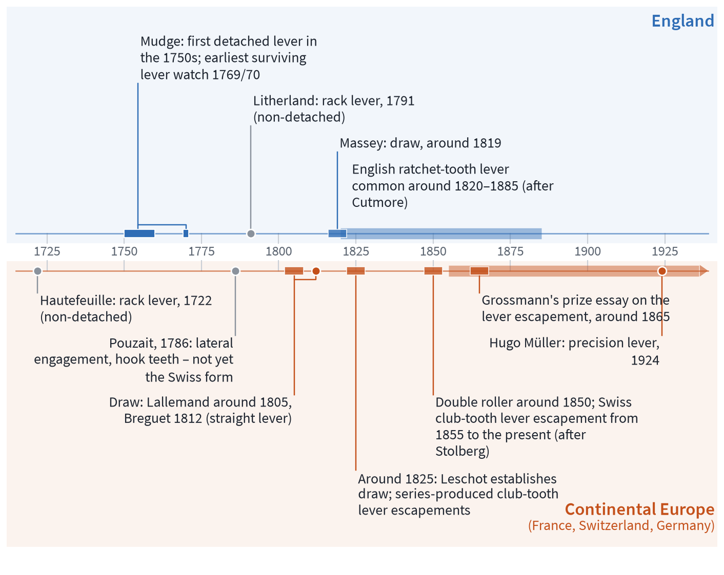
Timeline of the lever escapement in two lanes. The dates are given as ranges because the sources differ.
Who should be credited with the invention is also disputed. Trade journals often name Jean-Moïse Pouzait of Geneva as the inventor. He is said to have presented a lever escapement with angular teeth and divided impulse to the Geneva Société des Arts in 1786. Enders, however, shows that in Pouzait's escapement the escape wheel engaged the lever from the side and had hooked teeth, as in the virgule escapement. The date 1870, which you read in the trade press, also describes the escapement's adoption and not its invention. The date “around 1840” in the Pforzheim question set is too late for Leschot's draw, because Leschot established draw considerably earlier.
English, Glashütte and pin-pallet escapements
The English lever escapement has pointed teeth on a brass escape wheel, and the entire impulse lies on the pallet. Escape wheel, lever and balance are arranged at right angles to one another, and the larger drop costs energy. The Glashütte lever escapement after F. A. Lange had an escape wheel and lever of gold, covered pallets and a roller pin instead of a roller jewel. Hugo Müller's semi-unequal-armed precision lever brought visible pallets and banking screws. The pin-pallet escapement (Perron 1798, mass-produced by Roskopf from 1867) reaches a lift angle of 60 to 70°.
Feature | Swiss | English | Glashütte | Pin pallet |
|---|---|---|---|---|
Tooth | club tooth | pointed tooth | club tooth | tooth with impulse face |
Impulse | divided between tooth and pallet | entirely on the pallet | divided, equal on both pallets | almost entirely on the tooth |
Pallets | ruby, visible | covered in early examples | covered (Lange), visible (Müller) | steel pins |
Banking | two banking pins or fixed stops | banking pins | a banking pin pressed into the lever (Lange), banking screws (Müller) | at the root of the tooth |
Production period according to Stolberg | 1855 to today | 1800–1900 | 1850–1945 | 1870–1975 |
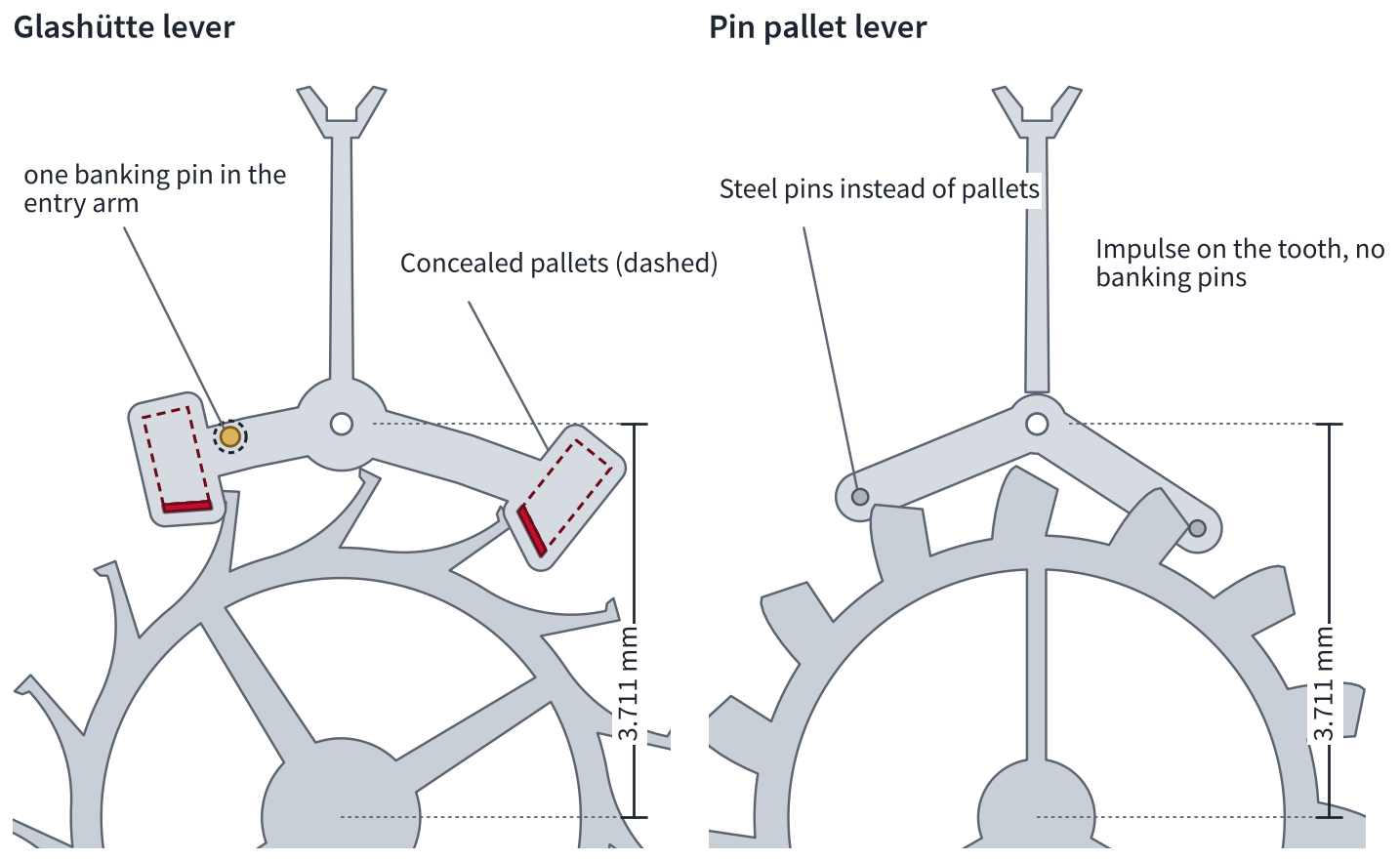
Glashütte lever and pin-pallet escapement at the centre distance of our model.
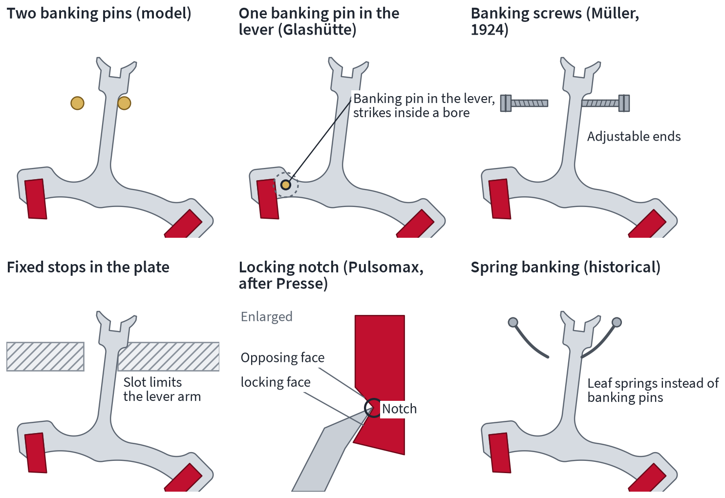
Types of banking, from the two banking pins to the rest notch. The Glashütte pin in the lever ends in a bore and strikes there; the dashed circle only hints at this.
The Swiss form prevailed because its club teeth hold the oil better and are more robust, and because it manages with a weaker mainspring. In return it demands greater manufacturing precision. According to the classification by Droz and Flores, it is a detached escapement with a flat-lying escape wheel that gives an impulse in every half-oscillation, indirectly via the lever. The standard DIN 8312 calls it the pallet lever escapement.
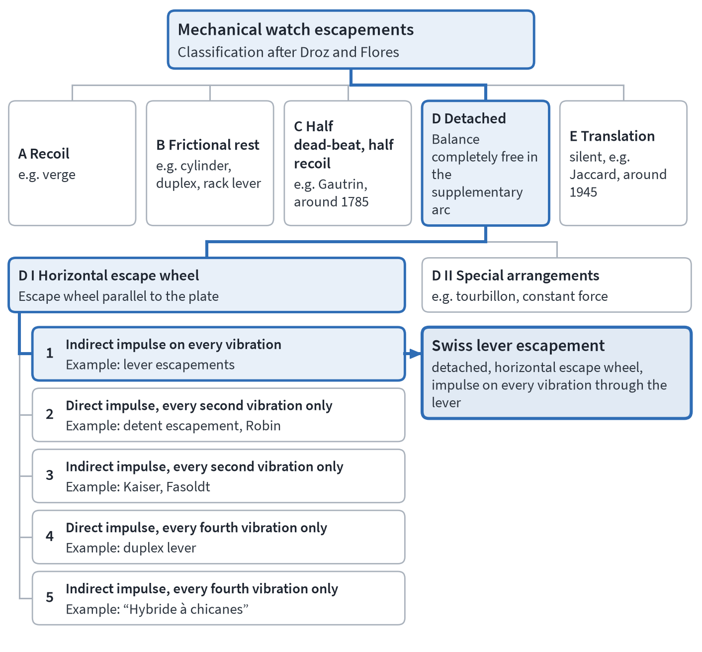
Classification after Droz and Flores: the path to the Swiss lever escapement.
New materials and direct impulse
Higher frequencies, new materials and new manufacturing processes have changed the Swiss lever escapement again and again, but its principle has remained the same. Alongside it there are alternative designs with direct impulse.
Innovation | What is different | Details |
|---|---|---|
Silicon (from 2001) | etched, light, non-magnetic, a semimetal and not a metal | in 2005 an escape wheel whose locking faces need no oil (Patek Philippe) |
Diamond (from 2005), DLC, LIGA | harder surfaces, electroformed components | diamond wheels first at Ulysse Nardin |
Pulsomax (Patek Philippe, 2008) | rest notch instead of stops, bridge between the horns instead of a guard pin, 16 instead of 20 teeth | up to 15% better efficiency according to the manufacturer |
Chronergy (Rolex, 2015) | lever and escape wheel of nickel-phosphorus | 15% more efficiency according to the manufacturer |
Constant (Girard-Perregaux, 2008) | silicon blade stores the impulse energy | constant force |
Clinergic 21 (FAR, 1960s) | 21 teeth, 36,000 vph | smaller balance, special lubricants |
Co-axial (Daniels), AP escapement, Dual Ulysse | direct impulse, for comparison | co-axial needs oil after all, AP 50 instead of 30% efficiency according to the manufacturer, Dual Ulysse ≈ 30° lift angle |
Part 3 at a glance and exam questions for the master course
Fork clearance, fork play at the instant of drop and horn clearance are three different clearances.
According to Bossart, the ladder of safety clearances is: run to the banking ≤ inner horn clearance ≤ guard pin clearance < outer horn clearance < depth of lock. The outer horn clearance must be larger than the guard pin clearance so that the impulse pin reliably finds its way into the fork after a shock. On the model, guard pin clearance on entry lies just above the run to the banking, and horn clearance lies above it along the whole horn.
In figures, the core rule is: a pallet moved by 0.01 mm gives around 0.3° at the lever. This change acts on its own depth of lock, on both drop locks and on the run to the banking of the opposite side. A banking pin changes the depth of lock, run to the banking, guard pin clearance and horn clearance on its own side 1 : 1, but not the drop lock.
There is only one lift angle, but it shows itself slightly differently in the model, in the running movement and on the timing machine. The 180° method calibrates the timing machine to the movement in question.
The escapement always makes the watch lose, more at low amplitude than at high. If a watch gains at low amplitude, additional effects in the oscillating system are involved.
1. What distinguishes horn clearance from fork play at the instant of drop?
Horn clearance is the distance through which the lever can be turned from the banking pin until the horn touches the impulse pin. It is checked in the supplementary arc. Fork play at the instant of drop is the play between the fork corners and the impulse pin at the instant the tooth drops. Only this play depends on the pallets (Bulova, Terms that are often confused).
2. Does draw become stronger if you pull a pallet out?
Pforzheim and Würzburg say yes; Smith, on the other hand, advises pushing the pallet in slightly if draw is too weak. On the model, moving a pallet practically does not change the draw angle at the banking pin (less than 0.01° per 0.01 mm), because the locking face slides in its own direction. At the pallet's locking corner, pulling out increases it by 0.30° per 0.01 mm on entry and decreases it by 0.30° on exit. Of all the adjustments, only adjusting the banking pins changes the draw angle at the banking pin. By stronger draw, Pforzheim and Würzburg therefore probably mean the deeper and thus safer lock (Draw in more detail).
3. Where does the ladder of safety clearances break down on our model?
On entry, the run to the banking (1.78°) is larger than half the depth of lock (1.63°). A guard pin clearance of half the depth of lock would therefore be smaller than the run to the banking there. The guard pin clearance set is 1.90°, with 1.36° of residual lock. The function as checked is what decides, because hardly any rule of thumb applies universally (The ladder of safety clearances).
4. On entry, the run to the banking, guard pin clearance and horn clearance are too large, and the drop lock is correct. What needs to be done?
Set the banking pin on the entry side narrower. It changes these values 1 : 1 and leaves the drop lock unchanged (Exam cases on the simulator).
5. The lock is too light. How can you tell from the fork play at the instant of drop which pallet you must change?
Pull out the pallet opposite the smaller play. If the lock is too heavy, push in the pallet opposite the larger play (Bulova, pallet-stone rule).
6. What guard pin clearance do the rules “half the lock”, “1° beyond the drop lock” and “at least the run to the banking” give on the entry side of our model?
The rule “half the lock” gives 1.63°, which is less than the run to the banking of 1.78°. The rule “1° beyond the drop lock”, measured from the banking pin, gives the run to the banking plus 1°, that is 2.78°, and only 0.48° of residual lock remains. The rule “at least the run to the banking” is met: 1.90° is set, with 1.36° of residual lock.
7. A watch runs lying flat but stops on the wrist. Why?
The escapement wedges. Because guard pin clearance or horn clearance is larger than the lock, the tooth ends up on the impulse face in a shock. The guard pin then presses against the safety roller, or the horn against the impulse pin (Wedging).
8. How do overbanking and rebanking differ?
In overbanking, the lever flips over to the other side in the supplementary arc. On the return swing the impulse pin strikes the outside of the horn instead of entering the slot, and the watch stops. In rebanking, the amplitude is too large, the impulse pin strikes the outside of the horn, and the watch gains (Knocking, rebanking, overbanking).
9. Is the tooth on the impulse face or the delayed impulse a fault?
The tooth on the impulse face is a fault, and the cause is too shallow a lock (Borderline cases: when the tooth drops onto the impulse face). The delayed impulse, by contrast, is normal, because when the watch is running the tooth dynamically meets the impulse face somewhat further along (Not a fault: the delayed impulse).
10. Why does a lever watch lose in the vertical positions?
Unlocking and the impulse after the dead point make the watch lose. In the vertical positions the amplitude is lower, and as a result the same intervention has a stronger effect (Why the Swiss lever escapement makes a watch lose).
11. Why does a 6498 show a risk of rebanking on a timing machine set to 52°?
The 6498 has a lift angle of 44°. An actual 280° therefore appears as 280° · 52/44 ≈ 331° (Determining a movement's lift angle).
12. How many degrees is 0.8 ms of beat error at 4 Hz and 250°?
It is π · 4 · 250° · 0.0008 ≈ 2.5° (Beat error in milliseconds and in degrees).
13. Why does the lift angle on the timing machine differ from the engagement on the model?
In between lie clearances, the dynamics of the fork, sound detection and the assumption of a sinusoidal oscillation. The 180° method compensates for these differences for the individual movement (The lift angle in more detail).
14. Who invented the Swiss lever escapement?
No single person. Mudge built the first detached lever in the 1750s, draw was added between about 1805 and 1825, series-produced levers with club teeth existed from about 1825, and the double roller from around 1850 (A short history).