The Swiss lever escapement – Part 2: Workshop
Part 2 · Workshop
Naming the escapement precisely
Part 1 showed how the escapement works. Part 2 goes deeper for the workshop and is intended to help you carry out every check of the escapement at the bench, interpret the findings, correct pallets, banking pins and guard pin in a targeted way, and narrow down faults instead of trying things out. After the chapter Moving the pallet stones and adjusting the banking, the exercise from the introduction can also be solved completely.
This chapter is the main location for all terms; later sections only refer back to it. From the next chapter on, the text follows the order of work at the bench: measure, check, adjust, narrow down faults, lubricate, final check.
Exercise: Our model as it came from the design stage, that is before adjustment, shows these values in lever degrees, measured as the angle through which the pallet fork turns about its staff (entry/exit): depth of lock 2.98°/2.34°, drop lock 1.76°/2.00°, run to the banking 1.22°/0.34°, clearance at the guard pin (guard pin clearance) 2.57°/2.07°. Which pallet must be moved in which direction, by how much, and what must still be checked afterwards?
This chapter explains the terms, and the section Chain of safety features and clearances explains guard pin clearance. The solution is under The exercise solved and can be reproduced on the digital pallet adjustment model.
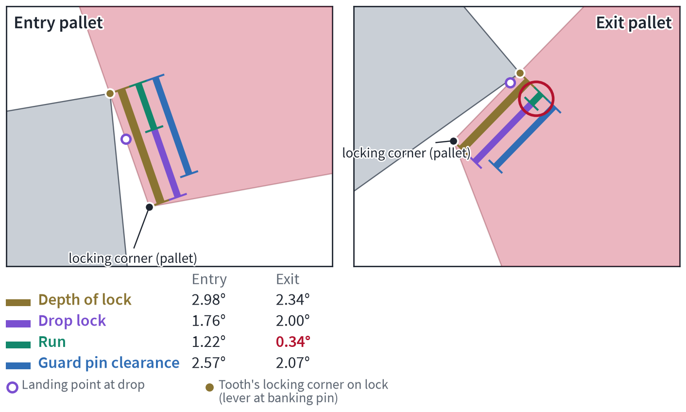
The complete finding on the model before adjustment: four measurements per pallet. At the exit, only 0.34° of run to the banking remains.
Our model in numbers
All images and animations show the model adjusted according to the workshop rule. Degrees at the escape wheel and balance degrees, like lever degrees, are measured about the staff of the component concerned. Centre distance escape wheel–pallet fork 3.711 mm, pallet fork–balance 4.038 mm; escape wheel with 15 teeth and outside diameter Ø 6.60 mm at 18,000 vph; the locking corners of both pallets lie 1.86 mm from the pallet centre; impulse pin distance, that is the radius of the impulse pin circle, 0.98 mm; lever ratio, the ratio of balance angle to lever angle during engagement, ≈ 3; pallet fork from banking pin to banking pin 13.6°; fork clearance 0.48°; lift angle ≈ 35°. The sequences are calculated quasi-statically, that is as slow motion without inertia.
Quantity | Entry | Exit |
|---|---|---|
Depth of lock (lever degrees) | 3.26° | 3.36° |
Drop lock (lever degrees) | 1.48° | 1.68° |
Run to the banking (lever degrees) | 1.78° | 1.68° |
Guard pin clearance (lever degrees) | 1.90° | 2.12° |
Residual lock with guard pin in contact (lever degrees) | 1.36° | 1.24° |
Horn clearance in the test position (lever degrees) | 2.58° | 2.79° |
Drop ending on this pallet (degrees at the escape wheel) | 1.80° | 2.03° |
Recoil of the escape wheel during unlocking (degrees at the escape wheel) | 0.39° | 0.48° |
Lift angle of the half-oscillation in which this pallet unlocks (balance degrees) | 34.90° | 34.55° |
Length of the impulse face from the pallet's locking corner to its let-off corner | 0.434 mm | 0.468 mm |
Faces and edges on the escape wheel, pallet fork, roller and banking
Each club tooth of the escape wheel has its locking face at the front (Zahnbrust in German). It is inclined back by about 24° from the radius so that only the tooth's locking corner, the edge at its locking face, rests against the pallet; this inclination is called the undercut. Behind it, at the head of the tooth, comes the tooth's sloping impulse face, which ends at the tooth's let-off corner.
But take care: the undercut must not be confused with the “draw angle”. It has nothing to do with draw, which arises at the pallet's locking face (Draw).
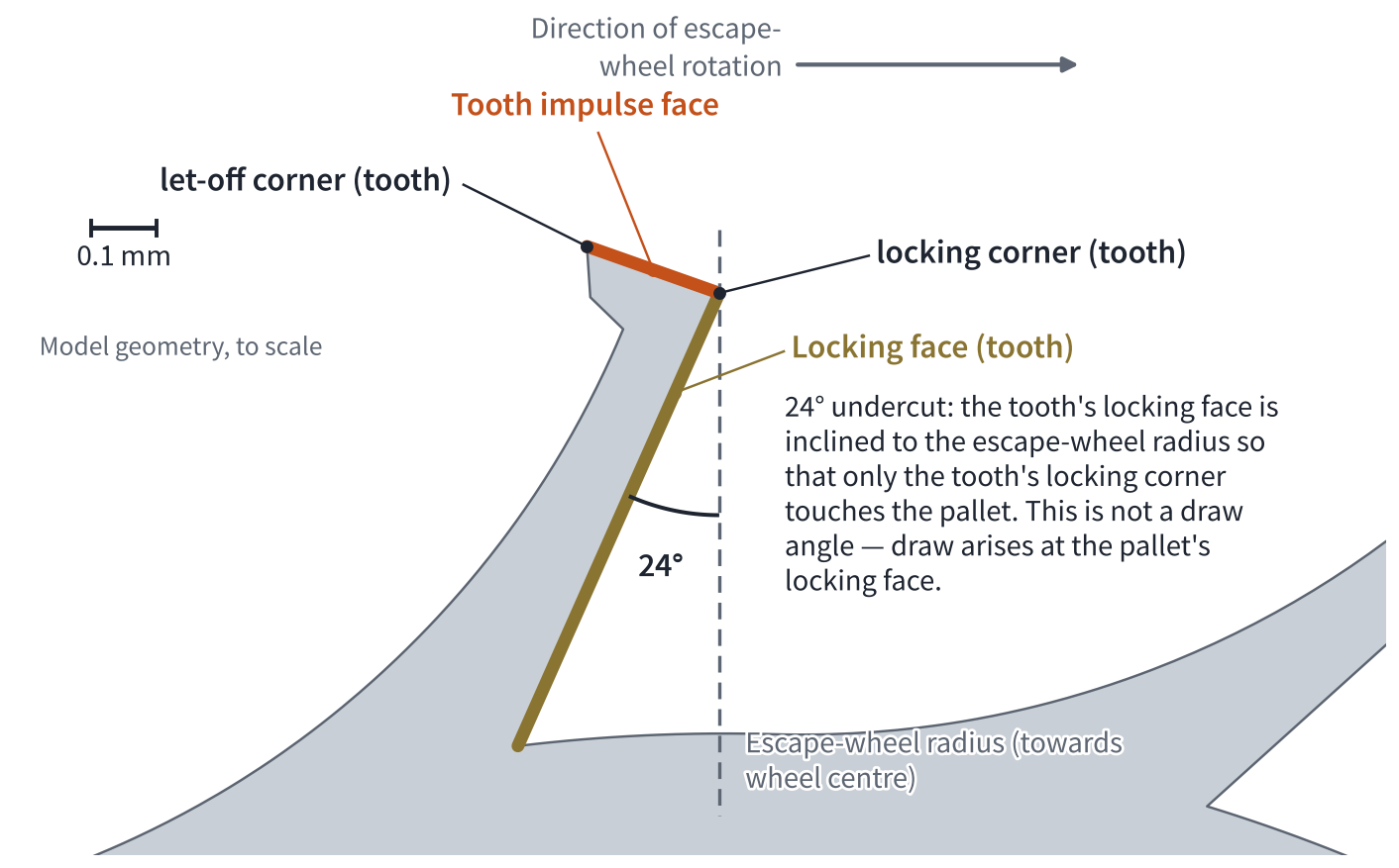
The club tooth and its faces.
The number of teeth depends on the beat rate and the era: 15 in pocket watches at 18,000 vph, as in our model; 20 at 4 Hz; 21 in the Clinergic 21 at 5 Hz from the 1960s; 16 in Patek Philippe's Pulsomax escapement (2008). Compared with the pointed tooth of the English lever, the club tooth has three advantages: impulse is shared between tooth and pallet, so the pallets and pallet fork can be lighter; a wedge-shaped gap remains between tooth and pallet, which holds the oil; and the tooth's blunter corner wears less than a thin point.
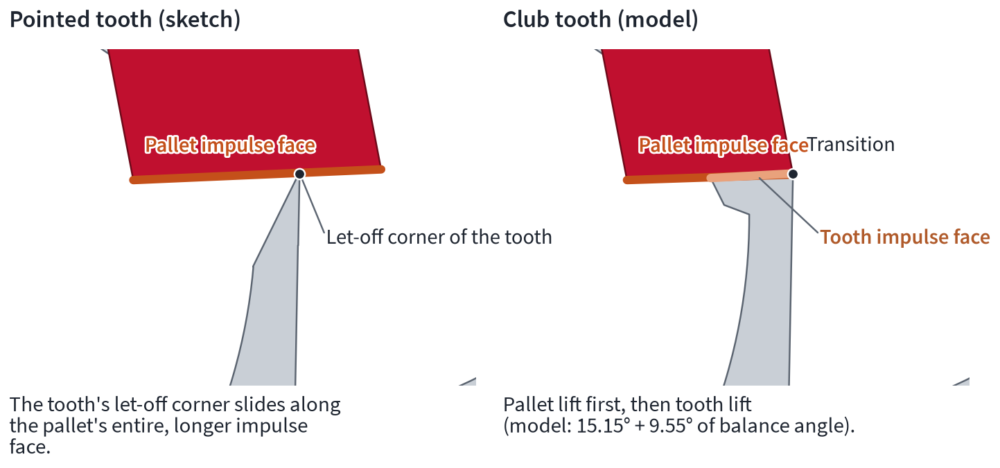
Pointed tooth and club tooth: with the club tooth, tooth and pallet share the impulse.
The two pallets also each have a locking face and an impulse face. The edge between them is called the pallet's locking corner, and the end of the impulse face the pallet's let-off corner; this is where the tooth leaves the pallet. Measured from the pallet's locking corner to its let-off corner, the impulse face in our model is 0.434 mm (entry) and 0.468 mm (exit) long respectively; all fractions such as “¼ of the impulse face” refer to this length. The pallets are set in shellac in slots in the pallet fork and can therefore be moved when warmed (Moving the pallet stones and adjusting the banking). Entry and exit pallets must never be interchanged, because they have different dimensions and angles.
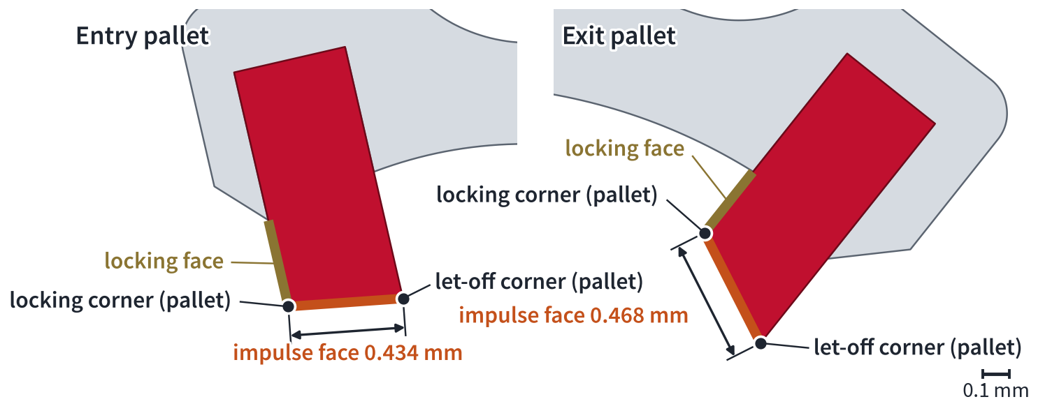
Entry and exit pallets with their faces and edges.
The fork sits at the rear of the pallet fork. Its slot receives the impulse pin; the side walls of the slot are called flanks, the edges at its mouth fork corners, and the two horns run out towards the outside. Between the horns, one level lower, sits the guard pin (all its names under The components at a glance), pressed in, riveted or, in high-quality movements, sometimes screwed. Today the impulse pin is usually semicircular, less often triangular; in the zero position, that is with the balance at the dead point, its flat side faces the pallet staff. In older watches it was ground to an elliptical shape; this is where the workshop word “ellipse” comes from.
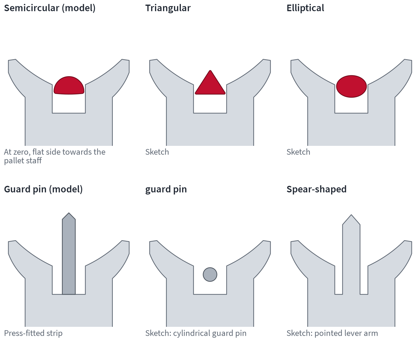
Impulse pin shapes in cross-section and shapes of the guard pin.
The double roller sits on the balance staff: two discs on a common tube. The large roller carries the impulse pin; below it lies the smaller safety roller with the passing hollow, through which the guard pin passes during unlocking. Fork and impulse pin work in the upper level, guard pin and safety roller in the lower; a tube upset while the roller was being staked on throws these heights out (Shape and position errors on the escape wheel, pallet fork, fork and pallets).
Today the double roller is usually made as a single part and pressed onto the balance staff with an interference fit. In older pocket watches you see various versions, because in the end it is the function that counts, and it makes no difference whether the ellipse sits directly in the balance arm or is set into a separate roller.
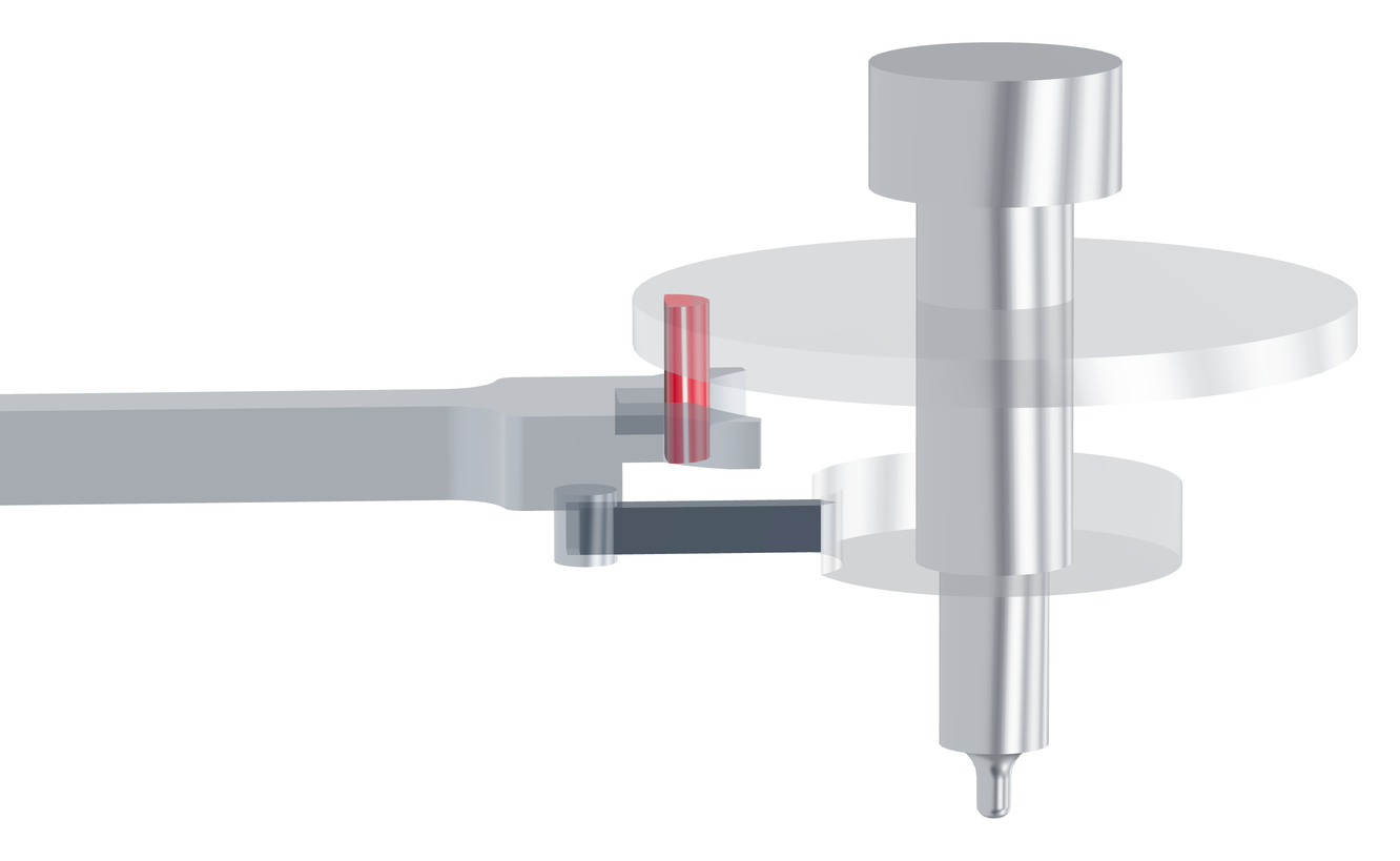
Double roller, fork and guard pin on two levels, seen from the side.
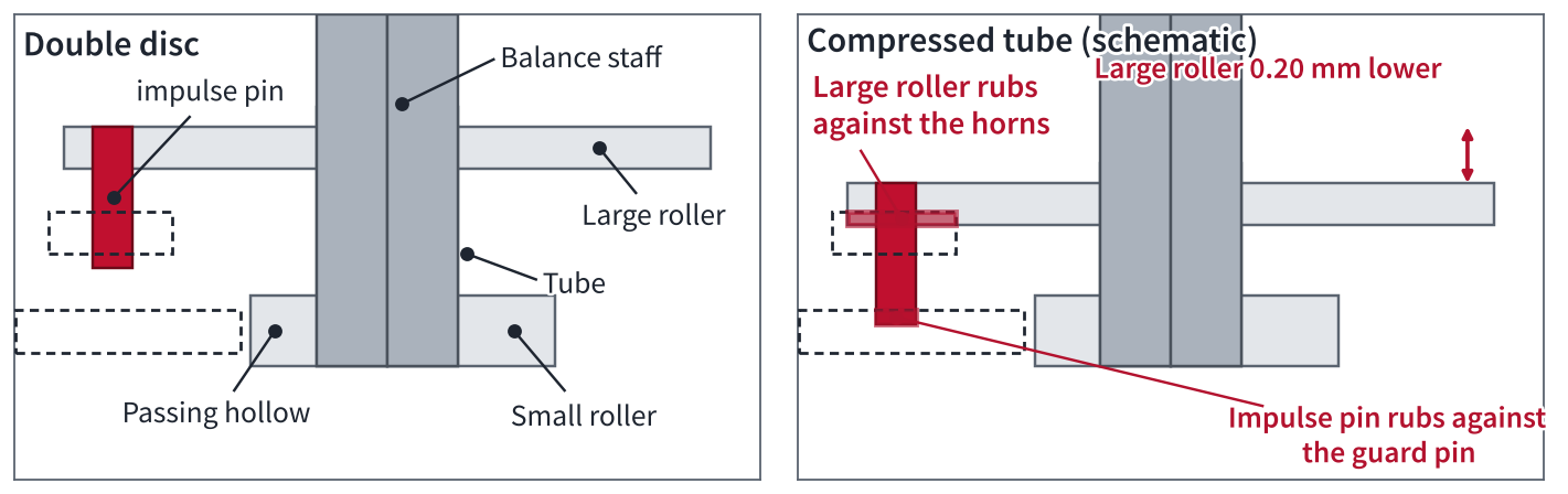
The double roller in section, and beside it with an upset tube (schematic).
The pallet fork's travel is limited by two banking pins in the mainplate, sometimes in the form of rotatable eccentric pins, or by fixed stops, that is recesses milled into the mainplate or bridge; these are the rule today. There were also special forms such as banking screws or sprung stops.
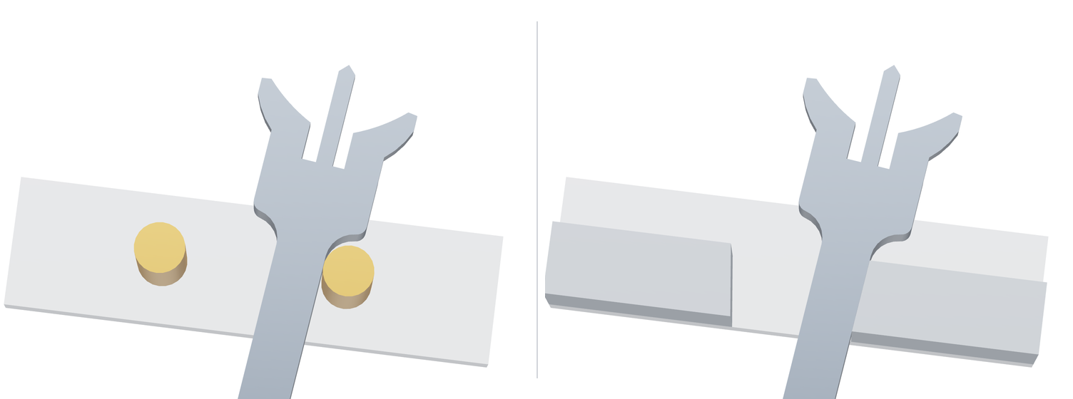
Left, the model's banking pins; right, as a variant, fixed stops in the mainplate (schematic).
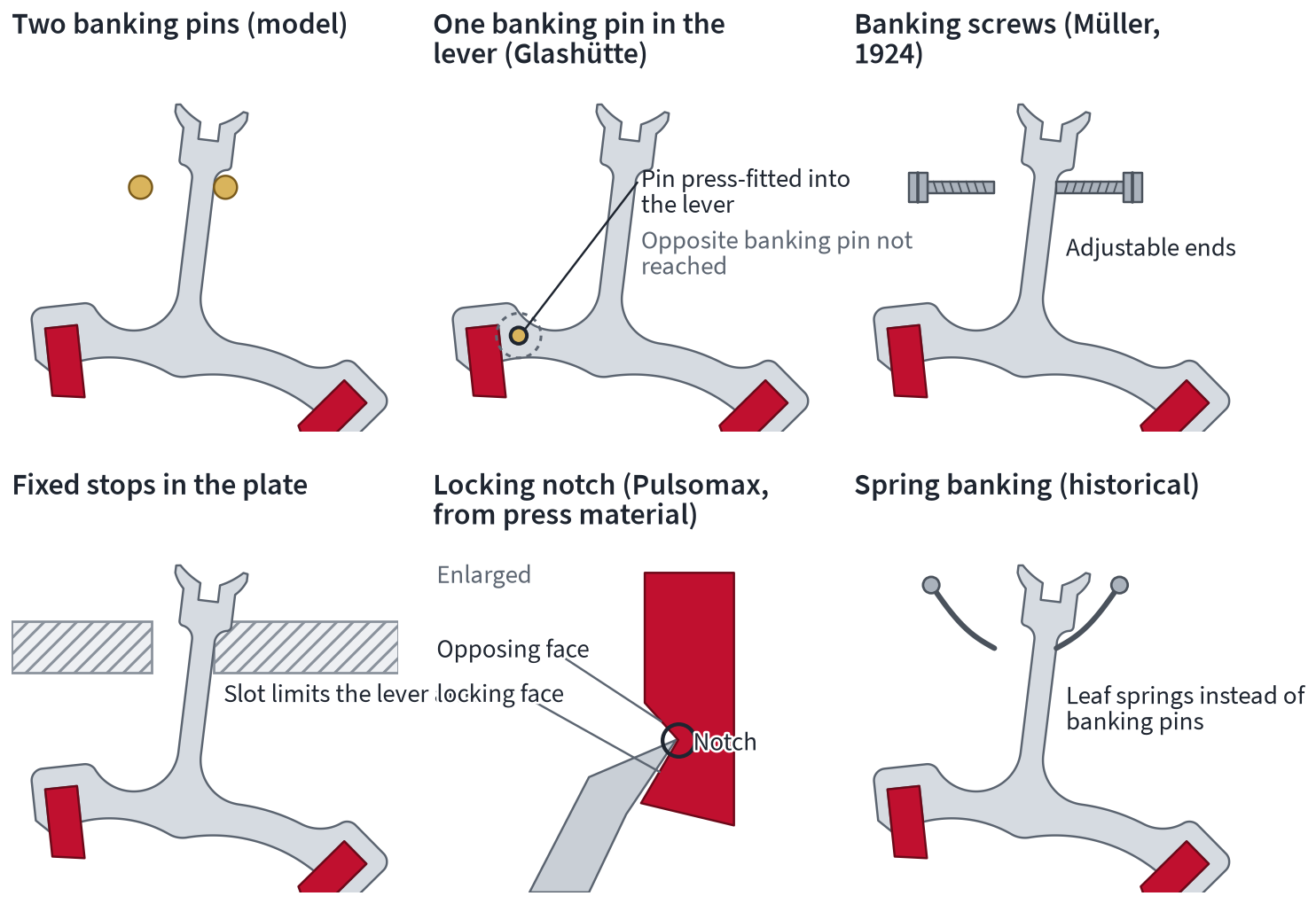
Types of banking, from banking pins to historical special forms. The Glashütte banking pin in the pallet fork ends in a hole and banks there; the dashed circle only indicates this.
Many components have several names; this article always uses the first:
In this article | Also called |
|---|---|
Escape wheel | Hemmungsrad, Gangrad |
Pallet | Klaue, Hebestein, Ankerklaue, Ankerstein, Hebungsstein |
Impulse pin | Ellipse, Hebelstift |
Horns | Zinken |
Guard pin | Sicherheitsstift, Lanze, Dard, Sicherheitsfinger and others (all under The components at a glance) |
Double roller | Doppelscheibe, Plateau, Hebelscheibe |
Depth of lock | Festhalteruhe, totale Ruhe, Gangtiefe |
Drop lock | theoretische Ruhe |
Draw angle | Anzugwinkel |
Assortment | Escape wheel, pallet fork and impulse pin as a set |
Swiss lever escapement | Steinankerhemmung (examination terminology) |
We do not use the word “Nachfall”, because it means different things: the drop in Schultz (1902), the run to the banking in Röseler and Schirmer.
But take care when reading manufacturers' documents: there the pallets are often called “Hebelsteine”, “Hebesteine” or “Hebungsteine”, and one manufacturer's translation even turns the impulse pin distance (“distance de cheville”) into a “distance of safety pin”.
The sequence with dimension lines
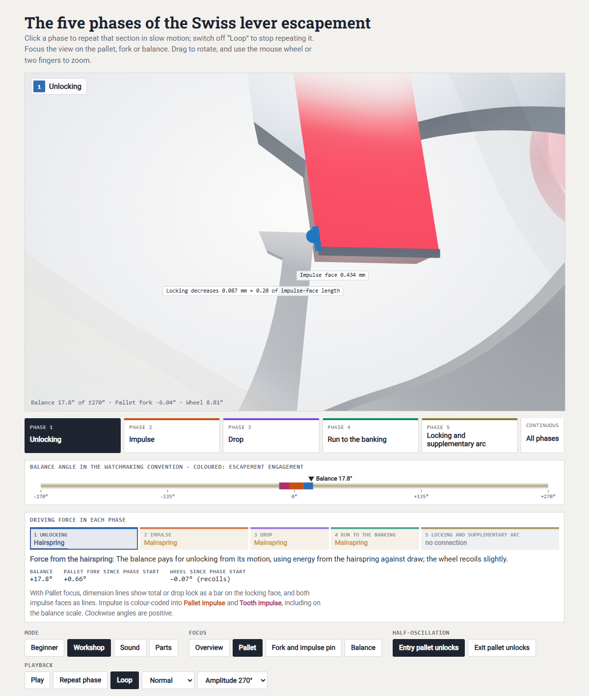 Open animation in a separate window
The five phases in workshop mode: dimension lines, angles and the bar “Force from the hairspring / from the mainspring”. Slow motion without inertia: positions from the real contacts, idealised animation.
In workshop mode, the phase animation shows what the bench needs: dimension lines, live angles and a bar showing whether the energy is currently coming from the oscillating balance or from the mainspring. Simulator and animations are calculated quasi-statically. Positions and angles are correct, but timings and impacts are idealised (more under What really happens).
Unlocking begins when the impulse pin strikes the flank of the fork and turns the pallet fork away from the banking pin. Because the locking face is inclined, the pallet pushes the escape wheel back a little in the process. Bossart gives about 0°15′ for 2° of lock; our model, with its deeper lock, comes to 0.39° (entry) and 0.48° (exit) respectively at the escape wheel. This brief recoil* is also described by Pierre-Yves Soguel, director of the Swiss chronometer testing institute COSC from 1997 to 2010, by the Bulova School of Watchmaking and by de Carle. At the same time, the guard pin enters the passing hollow of the safety roller.
*This is sometimes referred to in the oral part of the master's examination. Candidates are occasionally asked whether the Swiss lever escapement is a recoil, frictional-rest or detached escapement. The perfect answer includes that it is a detached escapement because of the free supplementary arc, but that a very slight recoil of the escape wheel takes place during unlocking, which the design requires for security against shocks.
As soon as the tooth's locking corner passes the pallet's locking corner, impulse begins, in two stages. First the tooth's locking corner slides over the pallet's impulse face: this is pallet lift. Then the pallet's let-off corner slides over the tooth's impulse face: this is tooth lift. Measured at the balance, these amount to 17.95° pallet lift and 6.2° tooth lift at the exit pallet, and 15.15° and 9.55° at the entry pallet. At the start of impulse, the fork catches up with the impulse pin: until then the impulse pin was pushing one flank ahead of it; now the other flank drives it. During impulse, the pallet fork turns through 7.98° at the exit pallet and 8.14° at the entry pallet.
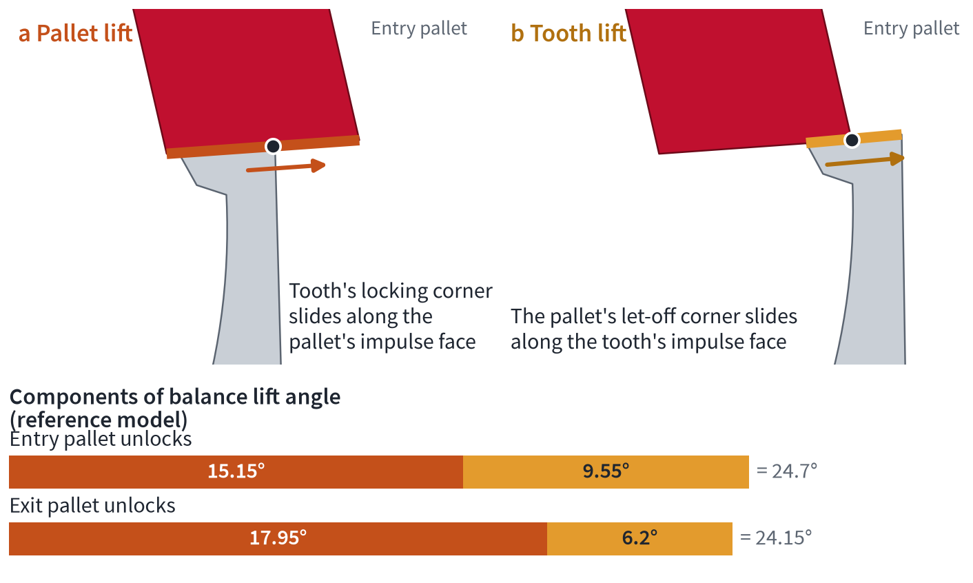
Pallet lift and tooth lift: impulse with the club tooth takes place in two stages.
At the end of tooth lift, the tooth leaves the pallet. The escape wheel turns freely until another tooth drops onto the locking face of the second pallet. The drop is this free angle of rotation of the escape wheel; in the workshop you see it as the distance from the pallet's let-off corner to the let-off corner of the tooth that has just dropped off. Because the sources name things differently here, we fix the names as they are used at the watchmaking school in Pforzheim: in the inside drop, the tooth leaves the entry pallet and drops onto the exit pallet; in the outside drop, it is the other way round. In the adjusted model, the inside drop is 2.03° and the outside drop 1.80°. Draw then pulls the pallet fork through the run to the banking up to the banking pin (Drop-lock point, depth of lock, run to the banking).
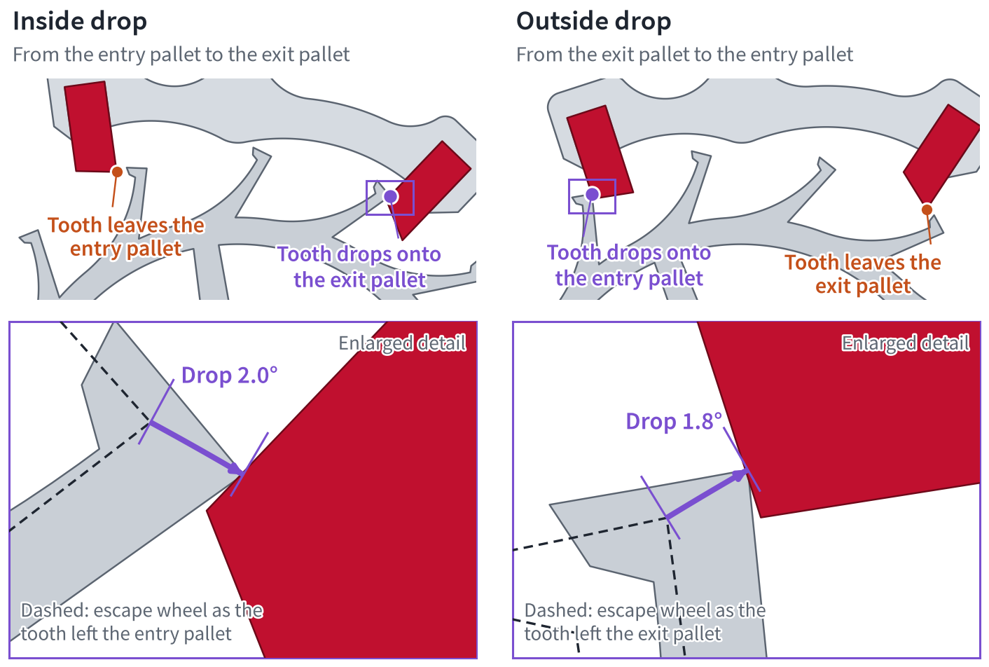
Inside and outside drop.
Phase | Where the energy comes from |
|---|---|
Unlocking with recoil of the escape wheel | from the balance's oscillating energy, which has to work against draw |
Impulse | from the mainspring, via escape wheel, pallet fork and fork |
Drop | from the mainspring, which drives the escape wheel while pallet fork and balance continue to move with their own kinetic energy |
Run to the banking | from the mainspring, via draw |
Lock and supplementary arc | no energy transfer, because balance and escapement are separate |
A simple check shows whether the angles fit together. The pallet fork's travel from one banking pin to the other is made up of three parts: unlocking and impulse at one pallet and the run to the banking at the other. When the exit pallet unlocks, these come to 3.84° + 7.98° + 1.78° = 13.60° in the model. When the entry pallet unlocks, they come to 3.78° + 8.14° + 1.68° = 13.60°. Measured directly from banking pin to banking pin, the result is 13.62°.
If you compare these values with the next section, you will notice a small difference. During unlocking, the pallet fork turns through 3.84° (exit) and 3.78° (entry) respectively, but the depth of lock is only 3.36° and 3.26° respectively. Both values are correct, because they measure the pallet fork's travel only up to different points. The depth of lock is the pallet fork's travel from the banking pin until the tooth stands exactly at the pallet's locking corner, measured on the stationary model. In the motion trace, that is the model's calculated sequence of motion, unlocking ends somewhat later. So that the two measurements do not get mixed up, all values for lock and clearances in this article come from measurement on the stationary model, and all values for the sequence come from the motion trace.
Drop-lock point, depth of lock, run to the banking
The dropping tooth lands on the locking face at the drop-lock point. The drop lock is the distance from this point to the pallet's locking corner, that is how deep the tooth already sits on the locking face when it lands. Draw then pulls the pallet fork on to the banking pin, and the tooth slides deeper. The depth of lock is the full depth when the pallet fork rests against the banking pin (total lock). This is exactly the travel the balance has to push back at every unlocking. The run to the banking is the lever travel in between, from the tooth landing to the banking pin. The drop-lock point is therefore the reference point for adjustment; how to find it on the movement is shown in the section Stopping at the instant of drop.
Key point: Drop lock + run to the banking = depth of lock. In the adjusted model, that is 1.48° + 1.78° = 3.26° at entry and 1.68° + 1.68° = 3.36° at exit (lever degrees).
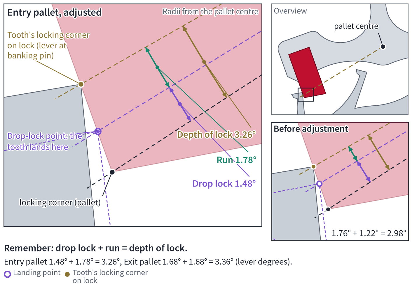
Drop lock and run to the banking together make up the depth of lock. Small, alongside: the model before adjustment.
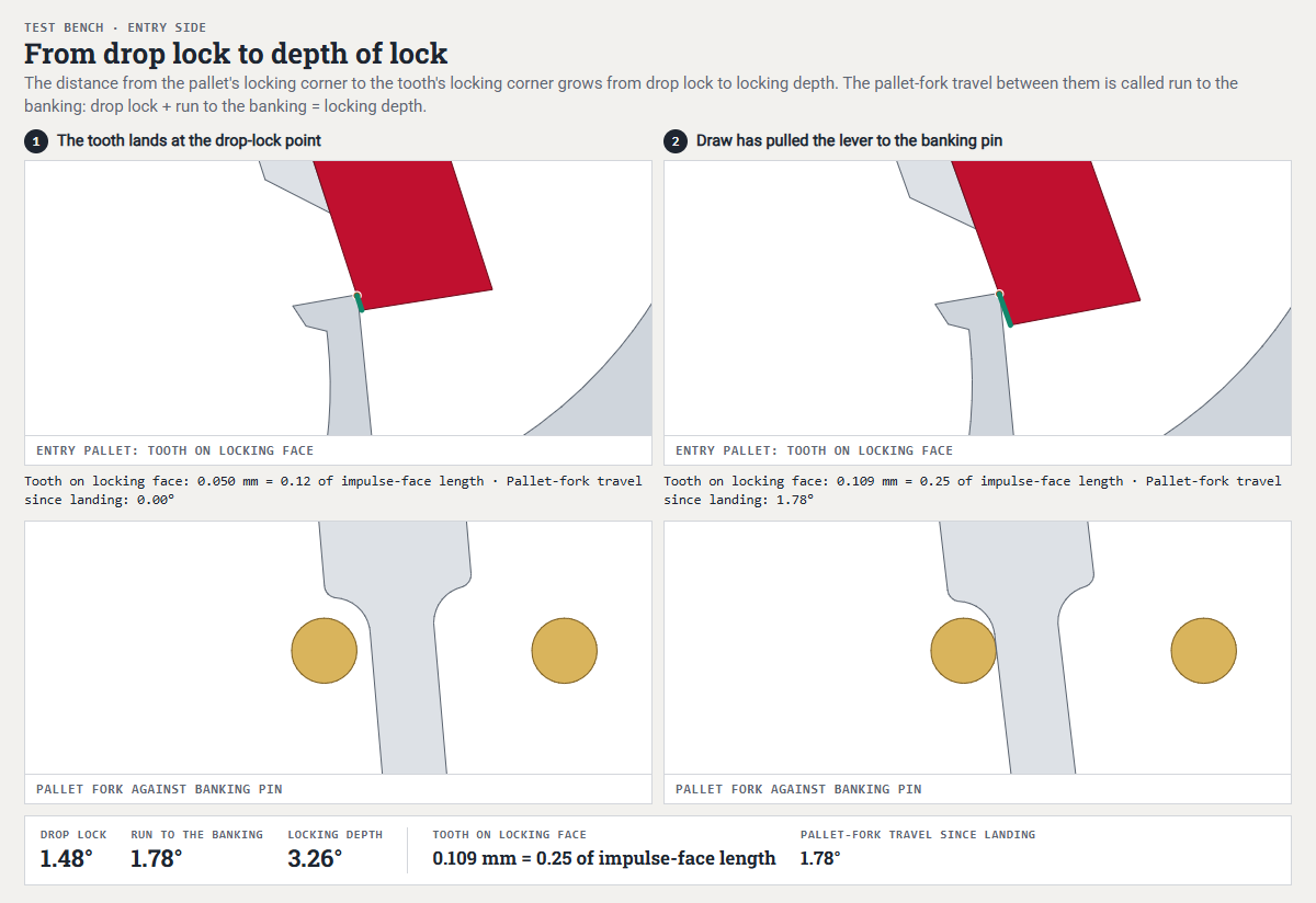 Open animation in a separate window
From the drop-lock point to full depth of lock: draw pulls the pallet fork against the banking pin.
The standard in this article is the workshop rule: drop lock ⅛, depth of lock ¼ of the impulse face, measured along its length from the pallet's locking corner to its let-off corner, equal on both sides and on all teeth. In the workshop I stick to the quarter of the impulse face, because angles this small cannot be seen by eye, whereas a length on the pallet is easy to estimate. Our model achieves a depth of lock of 0.25 and 0.24 of the impulse face respectively, and a drop lock of 0.12. Here the run to the banking is about half the depth of lock. Incidentally, in some movements the drop lock cannot be set symmetrically on both pallets at the same time as the depth of lock; in that case it is advisable first to set the depth of lock to a quarter of the impulse face and then to check whether the drop lock is safe. It does not have to be exactly ⅛ of the impulse face on both sides.
Helwig sums up why lock matters so precisely: if it is too small, the pallet fork starts moving of its own accord. If it is too large, unlocking becomes heavy, small oscillations become slower, and the watch loses in the vertical positions.
Some textbooks give lock in degrees: Bossart 1¾ to 2°, Wilkinson 1½° drop lock and ½° run to the banking. On our model, however, the quarter of the impulse face gives 3.26° and 3.36° respectively in lever degrees, considerably more. This is not a contradiction, because the textbooks' degree values are design angles: the designer rotates the line from the pallet centre to the locking point, that is to the pallet's locking corner, by this angle and begins drawing the tooth there. How many lever degrees a quarter of the impulse face gives depends on the distance from the locking point to the pallet centre; the fraction of the impulse face does not. On the model, the locking corners of the pallets lie 1.86 mm from the pallet centre; a quarter of the impulse face, around 0.11 mm, gives a good 3° there. If you mix degrees and fractions, you calculate wrongly; that is why it is best always to state the reference quantity.
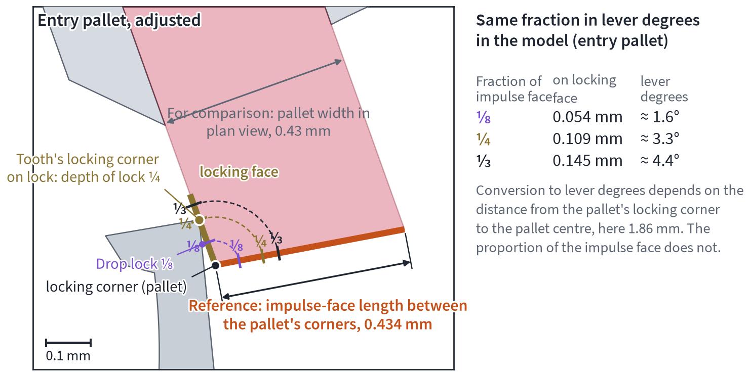
One eighth, one quarter, one third of the impulse face.
Other textbooks divide lock differently. Because the guide values have changed along with the watches, here are the figures once more by era:
Source | Era, type | Lock | Run to the banking | Share of depth of lock |
|---|---|---|---|---|
This article's workshop rule (depth of lock ¼ also in the Pforzheim course notes) | today's workshop | drop lock ⅛, depth of lock ¼ of the impulse face | the rest | ≈ 50% |
Bossart, Fachkunde für Uhrmacher | 1950, pocket watch | depth of lock 1¾–2° | 15–30′ | 12–29% |
Wilkinson | 1916, American pocket watch | drop lock 1½° | ½° | 25% |
Röseler after Schirmer | 1988/2015, wristwatch | drop lock 1.0–2.5° | ⅓ of the drop lock | 25% |
Theorie der Uhrmacherei | current Swiss textbook | depth of lock at most ¼–⅕ of the impulse face | 30′–1° | – |
Bulova School of Watchmaking, “banking to a drop” | around 1945, USA | drop lock ≈ ¼ of the impulse face width, depth of lock at most ⅓ | ⅓ of the drop lock | 25% |
Technical drawing textbook sheet, origin unknown, exercise “small lever watches” | – | 2°40′ | 1°10′ | 44% |
Why have a run to the banking at all? It is the necessary tolerance for runout, pitch and pivot play. Without it, with a slightly longer tooth or an escape wheel that is out of round, the pallet fork reaches the banking pin before the tooth has left the impulse face, and the escapement locks up (Pforzheim course notes; borderline case under Borderline cases). Claußen calls it the space reserve for teeth of unequal length. It also gives draw a distance over which it pulls the pallet fork to the banking pin. The run to the banking must therefore be as large as the escape wheel and pivots require, and must not become larger than the guard pin and horns allow. Whether to keep it rather tight or rather generous is an old point of dispute (What really happens).
In the animation, you can read lock at the balance. This shows the lever angles magnified by the lever ratio. In our model, this is about threefold: unlocking costs 10.2° (entry) and 10.4° (exit) respectively at the balance; in Helwig, with a ratio of 1 : 3½, 1½° of lock becomes 5¼° of balance travel. As a rule of thumb for the eye, Helwig and Jendritzki give a lock of about ⅔ of the thickness of a balance pivot.
Draw
The pallet's locking face does not point towards the centre of the escape wheel but is inclined to it by the draw angle. The tooth's pressure therefore draws the pallet into the escape wheel and brings the lever, with its lever arm, against the banking pin. This draw holds the lever securely against the banking during the supplementary arc and brings it back immediately after a shock. This safety feature does not come free: at every unlocking the balance has to work against draw and loses energy as a result.
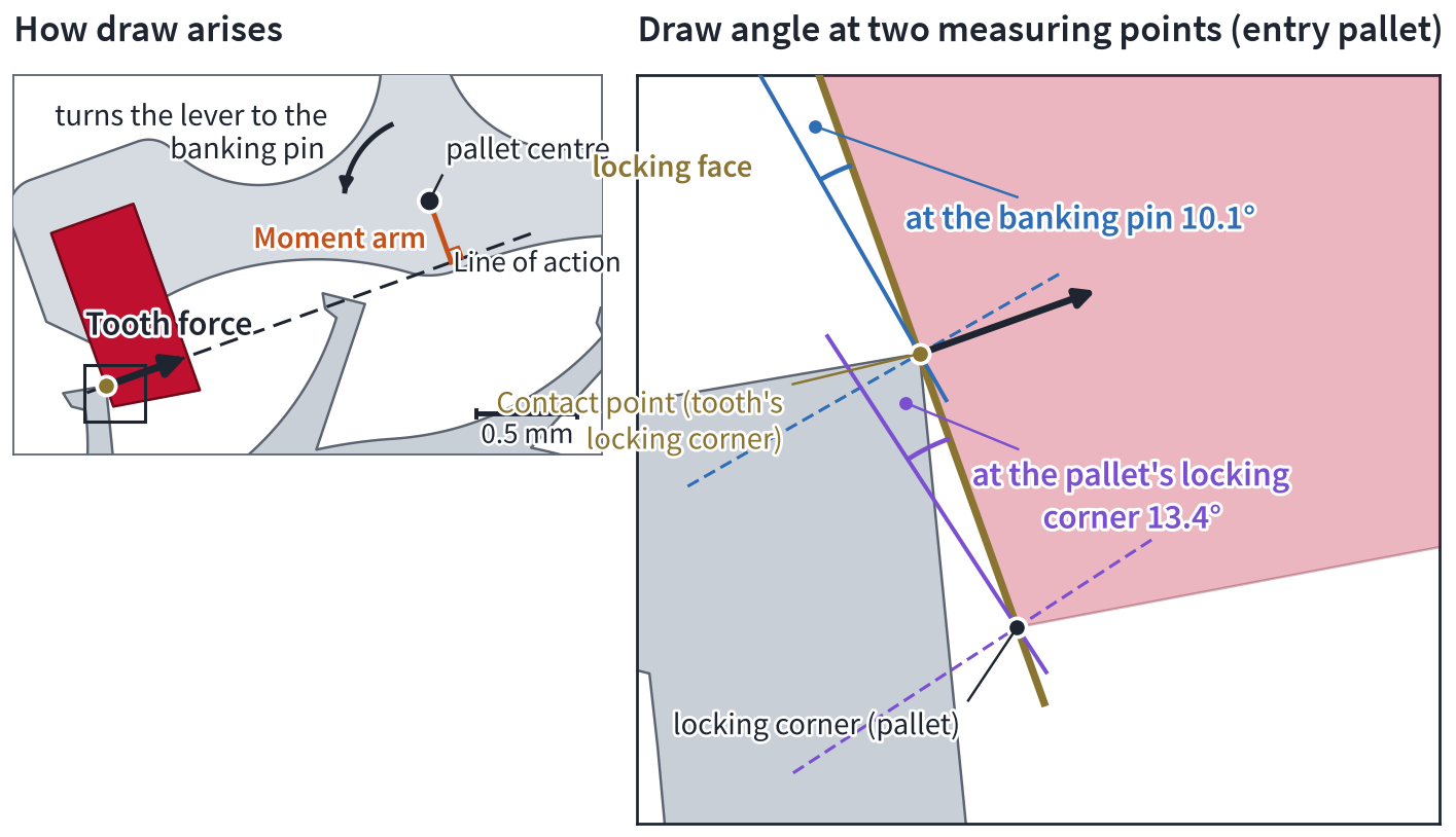
How draw arises: the line of action of the tooth's force passes beside the pallet centre, so the force turns the lever against the banking pin.
Is a lever without draw “detached”? The Pforzheim question set on the Swiss lever escapement says that only draw makes it a truly detached escapement. Brüggemann (Hemmungsatlas) and Droz/Flores, by contrast, define “detached” by the contact-free supplementary arc; by that definition, Thomas Mudge's lever of the 1750s was already detached, although it had no draw. Our suggestion: Mudge's lever was already detached in the sense of the classification, but it only stays reliably detached thanks to draw, which brings it back to the banking after every shock. Draw was added between about 1805 and 1825 (A short history).
For draw to work, the draw angle must be larger than the friction angle of steel on ruby, that is, the inclination at which the tooth begins to slide on the face; the textbooks put it at about 9° (for the dispute over the coefficient of friction, see Draw in more detail). Typical values are 12 to 16°, usually a little more on exit than on entry; the modern Nivarox 20.3 escapement sets the locking face at 15° to the wheel radius. Our model has two values, depending on where you measure. With the lever at the banking pin, measured at the contact point of the tooth's locking corner and from the perpendicular to the lever radius, they are 10.1° on entry and 15.5° on exit (from the wheel radius, as Nivarox measures, 9.9° and 14.7°). At the pallet's locking corner, where Bossart measures with the crosshairs, they are 13.4° and 12.1°.
This is not a contradiction. The locking face is flat, but the reference line is perpendicular to the lever radius, and this radius points in a slightly different direction to the pallet's locking corner than to the contact point: by the angle through which the lever turns during unlocking from the banking pin to the pallet's locking corner, that is, by roughly the depth of lock of a little over 3°. The draw angle changes by this amount along the locking face: on entry it increases towards the pallet's locking corner, on exit it decreases. This is why, at the banking pin, the exit side has the larger draw angle, and at the pallet's locking corner the entry side does; in the model, the textbook rule “a little more on exit” applies only at the banking pin. The smallest draw angle on the locking face lies, on entry, at the banking pin (10.1°) and, on exit, at the pallet's locking corner (12.1°); both are above the friction angle of about 9°, the entry side only just. Depending on where they measure, textbooks mean different things by the draw angle. Anyone comparing values must therefore always check the reference points (Draw in more detail).
If draw is too weak, the lever wobbles, the guard pin rubs, and on its return the impulse pin may not find its way into the fork. If it is too strong, unlocking becomes heavy, the amplitude falls, and in the extreme case the watch stops on the lock. The Würzburg master course advises: better slightly too strong than too weak.
Draw cannot be adjusted in the workshop; it is already fixed in the design of the watch. It is checked with the draw test. Depth of lock and draw are two different things (Terms that are often confused).
Key point: On the entry side the draw angle increases during unlocking; on the exit side it decreases.
Chain of safety features and clearances
In the supplementary arc the balance is free, and meanwhile draw holds the lever against the banking. The chain provides safety in the event of a shock: draw and banking hold the lever; if something knocks it, the guard pin comes to rest against the safety roller; when the guard pin is in the passing hollow, that is, shortly before and after the dead point, the horns take over at the impulse pin. For the handover to work, the impulse pin must engage deeply enough in the fork: along the whole horn, no shock may bring a tooth into impulse (Depth of engagement).
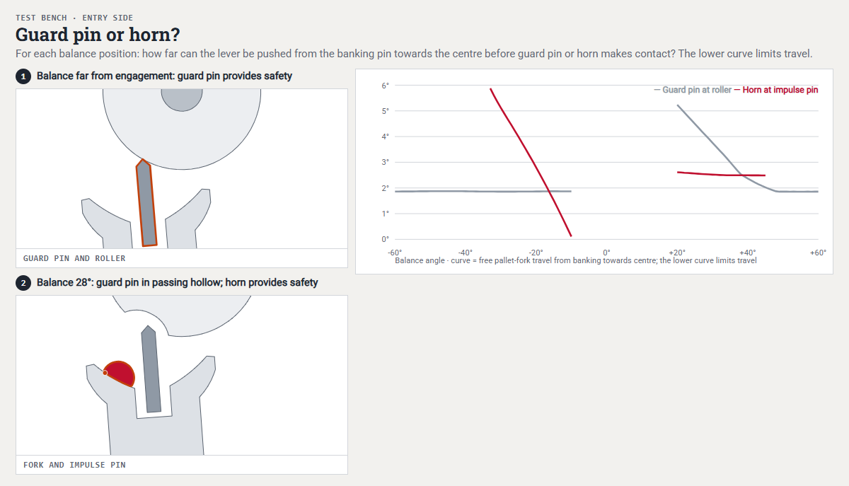 Open animation in a separate window
The handover: first the guard pin provides safety at the roller; in the passing hollow the horns take over.
The clearances, or play, are the small distances the lever can travel before the next safety feature takes over. At the impulse pin, following the Bulova School of Watchmaking, we distinguish three clearances. Fork clearance (jewel pin freedom) is the sideways play of the impulse pin in the fork slot, in the model 0.48° of lever travel from flank to flank, that is, both sides together. Fork play at the instant of drop (jewel pin shake) is the play between the fork corners and the front and back of the impulse pin at the instant the tooth drops; Brinkmann, like Pforzheim, calls it “Hörnerluft” (horn clearance), hence some confusion. Horn clearance (jewel pin clearance) is the lever travel from the banking pin until the horn touches the impulse pin, checked shortly after the impulse pin has left the fork. Finally, guard pin clearance is (in the supplementary arc) the lever travel from the banking pin until the guard pin touches the safety roller; it must always be slightly smaller than the lock, so that the tooth stays securely on the locking face when the guard pin is pressed against the roller.
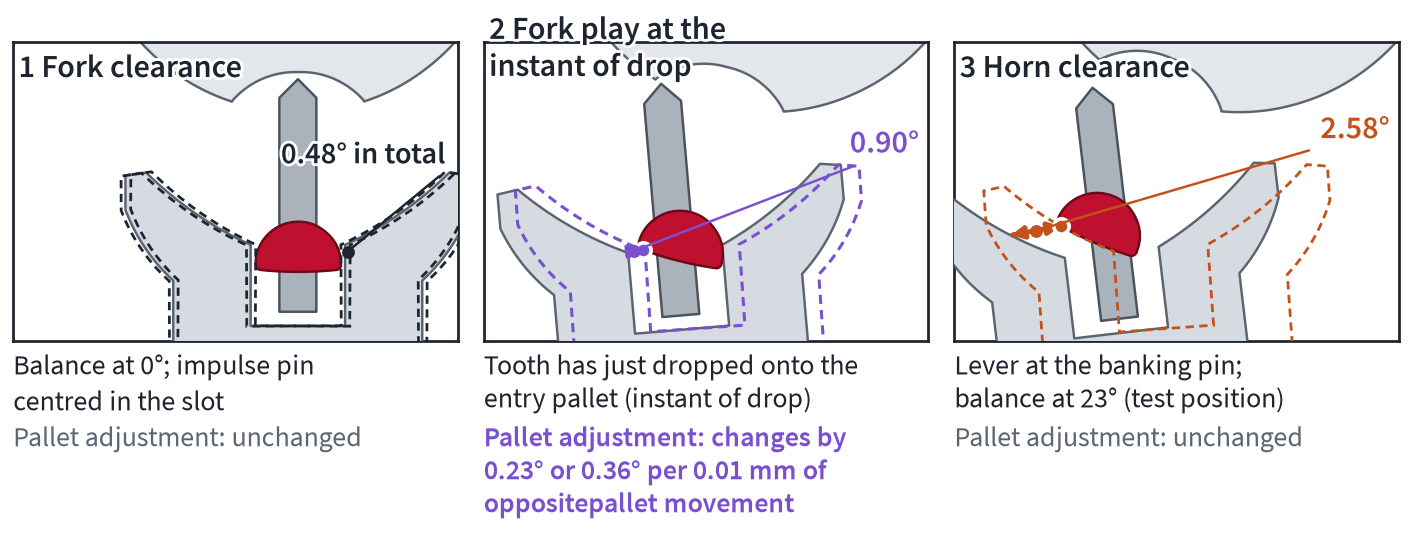
Three clearances at the impulse pin: fork clearance, fork play at the instant of drop, horn clearance.
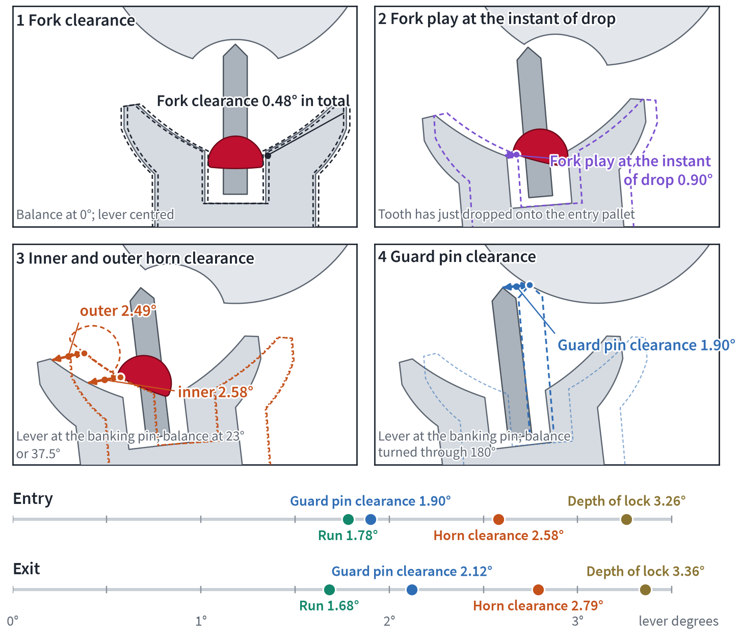
All clearances at a glance, with the ladder of safety clearances below.
From this follows the guiding rule: every clearance is smaller than the lock it protects. In the adjusted model, the order in lever degrees, entry/exit, is: run to the banking 1.78°/1.68° ≤ guard pin clearance 1.90°/2.12° < horn clearance 2.58°/2.79° < depth of lock 3.26°/3.36°. With the guard pin in contact, 1.36° and 1.24° of lock remain respectively, that is, 0.42 and 0.37 of the depth of lock. The textbooks call for about half the lock (Helwig, Theorie der Uhrmacherei), but on entry this is not possible with the workshop rule: according to Bossart's order of clearances, guard pin clearance is at least as large as the run to the banking, and at 1.78° this is already larger there than half the depth of lock, 1.63°. The point of dispute and the whole ladder are dealt with in the section The ladder of safety clearances and the rebanking limit.
Nor does our model meet the textbook sequence “inner horn clearance at most equal to guard pin clearance” (Bossart, Theorie der Uhrmacherei) in the checking position. Textbook values are design figures or makeshift figures; for me, what matters is the function as checked, and hardly any rule of thumb applies universally. Here the guard pin holds the tooth securely on the lock, and the horn catches the impulse pin while 0.68° and 0.57° of lock respectively still remain. I keep guard pin clearance nicely small but distinct: the guard pin must never rub, but it must be long enough that the tooth cannot leave the locking face when you move the lever back and forth, because it is still at work at the start of unlocking too.
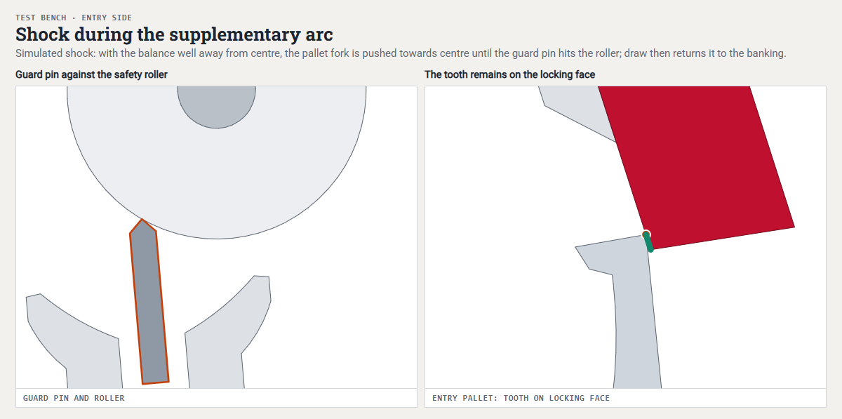 Open animation in a separate window
A shock in the supplementary arc: the guard pin rests against the roller, the tooth stays on the lock, and draw brings the lever back.
The outer shape of the horns is no accident either: it is designed so that the impulse pin can strike them there without damage. This happens when, in overbanking, the lever jumps to the wrong side in the supplementary arc, for example after a shock with a guard pin that is too short; on its return the impulse pin hits the outside of the horn instead of the slot, and the watch stops. In the second case, rebanking, the amplitude is too large: at the end of the supplementary arc the impulse pin strikes the outside of the horns, and the watch gains heavily. Where rebanking begins is given under The ladder of safety clearances and the rebanking limit.
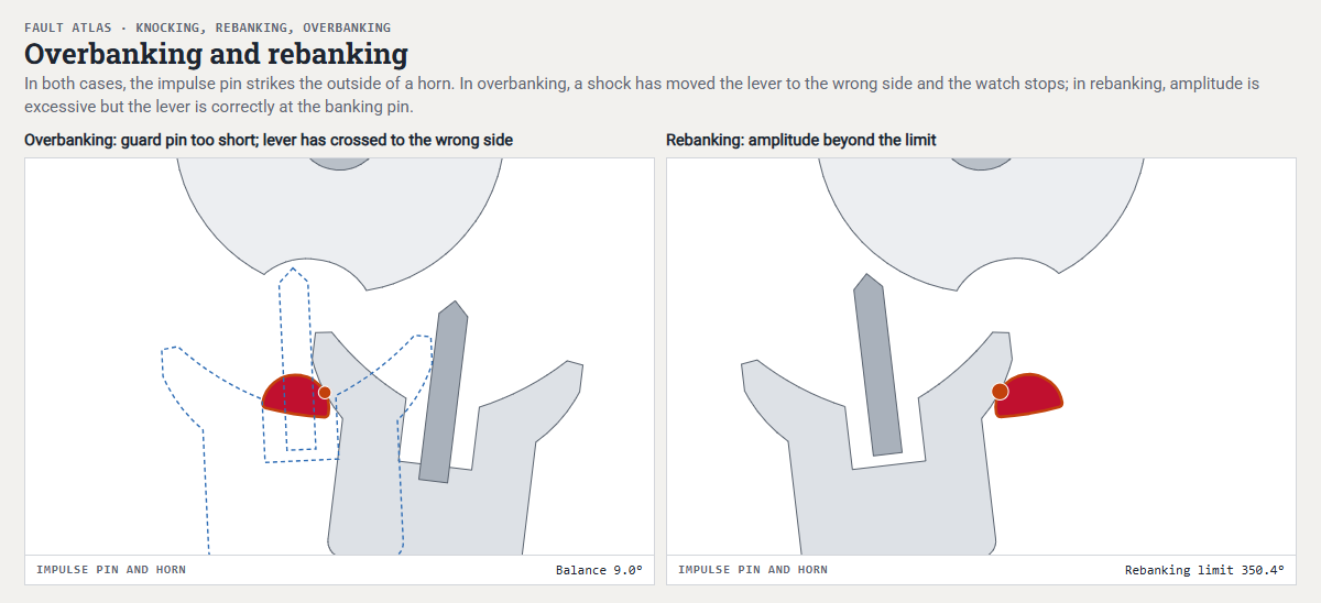 Open animation in a separate window
Right, rebanking: if the amplitude is too large, the impulse pin strikes the back of the opposite horn, in the model from 345.9° or 346.4° amplitude. Left, overbanking; the fault atlas shows the sequence.
The chain applies in height too: shock-protection systems let the balance move axially by 0.05 to 0.06 mm, so the guard pin and safety roller, and the impulse pin and fork, must overlap by more than endshake plus shock travel (design rule under Fork, roller and the chain of safety features as a design rule).
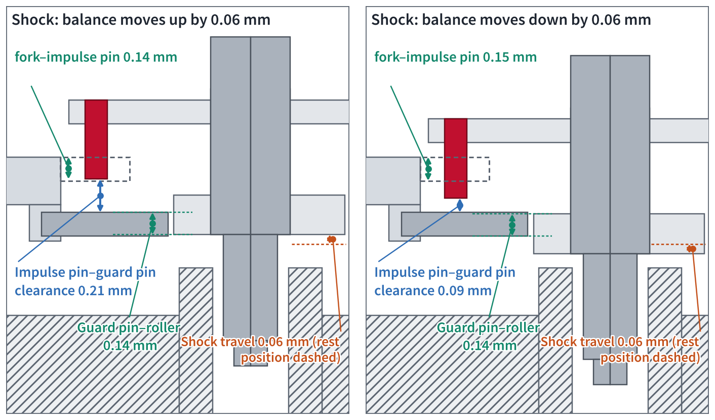
Shock travel and vertical overlap: even during a shock, the guard pin must still meet the roller.
Key point: The guard pin and horns let the lever move only so far that the tooth stays on the lock.
What you hear: five impacts, three sounds
A half-oscillation consists of five impacts: the impulse pin strikes the fork, the tooth strikes the impulse face, the fork drives the impulse pin, the tooth drops onto the locking face, and the lever arm strikes the banking pin. Soguel describes a tick in exactly this way: five impacts that the ear cannot separate; only an oscilloscope can. This is the bridge from the five phases to the timing machine.
Three bursts are audible, the last one the loudest. The drop and the banking-pin impact practically merge into a single impact (What really happens). In the quasi-static model they are 5.25° or 5.65° of balance angle apart, depending on the half-oscillation, a little over 1 ms at 280° amplitude. This comes from the geometry: in the rigid model the fork continues to push the impulse pin after the drop until the lever rests against the banking pin (The lift angle in more detail). This does not refute the observations on the dynamics in the literature.
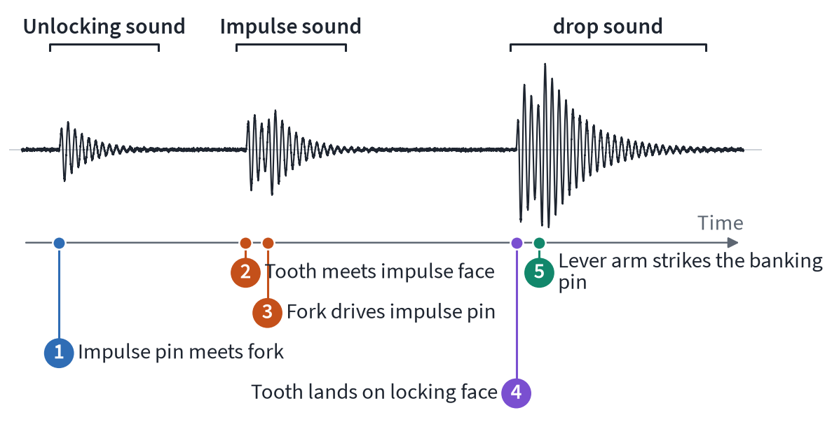
Five impacts of the Swiss lever escapement.
In interpreting the three bursts, we follow the latest version from the timing-machine manufacturer Witschi (2025). The unlocking sound arises when the impulse pin strikes the fork. The impulse sound arises when the tooth strikes the impulse face and the fork drives the impulse pin. The drop sound arises when the tooth drops onto the locking face and the lever strikes the banking pin. Older documents from the same manufacturer still interpret the second burst as the pallet lifting off the escape wheel; this interpretation is outdated.
What the timing machine detects as the start and end of a burst depends on the gain control: it picks up the first burst at its start and the third at its peak. For rate and beat error it uses the first burst; for amplitude, the time from the first to the third (Measure first: the escapement on the timing machine; what remains of the lift angle in this measurement is given under The lift angle in more detail).
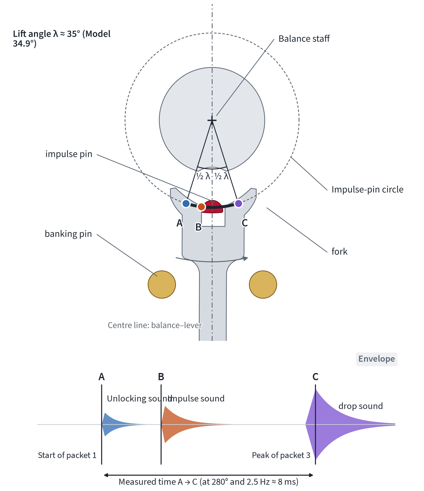
Lift angle and three sounds: the timing machine measures from the start of the first burst to the peak of the third. Envelopes, schematic.
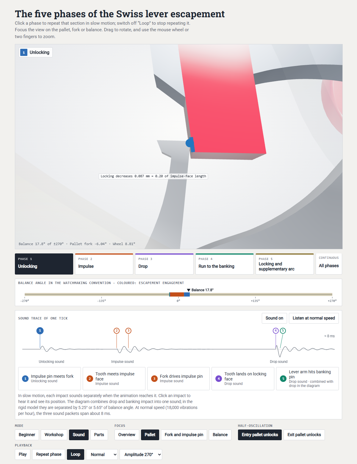 Open animation in a separate window
In sound mode, after “Sound on”, the impacts sound individually as soon as the slow motion reaches them; the drop and the banking-pin impact sound together.
Measure first: the escapement on the timing machine
What does the timing machine reveal about the escapement before the movement is opened? Quite a lot: whether it unlocks evenly, whether enough energy is transferred to the balance, whether something is rubbing. For now, this chapter is meant to help with interpretation without formulas; the calculation follows later under Timing machine and lift angle in formulas.
What the timing machine measures and which values apply
The timing machine (timegrapher), the instrument that picks up the movement's beat sounds through a microphone, reads three values from the three sound bursts: the rate in seconds per day from the interval between the beats; the beat error, that is, the time difference between tick and tock; and the amplitude from the time from the unlocking sound to the drop sound. For the amplitude it also needs the movement's lift angle, which has to be entered (Why the displayed amplitude is only an estimate).
You take this value from the manufacturer's documentation. Most wristwatches lie between 49 and 54°: current ETA movements at 49 to 51°, older ETA data sheets give 52 to 53°, and the ETA 2750 family, at 4 Hz with 20 teeth, 54°.
Movement | Lift angle | Source |
|---|---|---|
older pocket watches | 30–36° | Bossart, Brinkmann, Helwig, Jendritzki |
Unitas/ETA 6497, 6498 | 44° | ETA |
Valjoux 7733 | 48° | ébauche data sheet |
Valjoux/ETA 7750 | typically 49° (until 2010: 50°) | ETA |
ETA 2824-2 | 50° | ETA |
ETA 2892A2 | 51° | ETA |
ETA 2750 family, 4 Hz, 20 teeth | 54° | ETA |
pin-pallet movements | up to 70° | Witschi table, Jendritzki |
our model | ≈ 35° | simulator |
Witschi's calibre table, with around 2,080 calibres, shows how wide the range is: 34 to 70°, median 52°, just under two thirds between 50 and 54°, a few lever movements at 58 to 61°. For a particular calibre it is a third-party source; the manufacturer's sheet takes precedence. In the workshop you mostly come across values of 30 to 52°, sometimes more. If the manufacturer's value is missing, the 180° method helps.
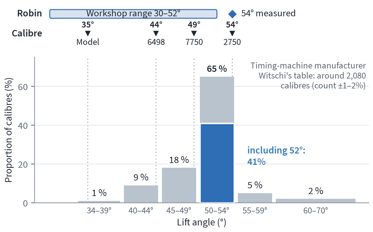
Lift angles of around 2,080 calibres according to the Witschi table.
Manufacturers' values are nominal values. For the 7750, ETA explicitly states “typically 49°” and corrected the value from 50 to 49° in 2010. If you measure with the Witschi table value (52°), you read around 297° on the screen for an actual 280°; with the old ETA value of 50°, around 286°. If in doubt, the current manufacturer's sheet applies to the current version.
Measurements are taken from 10 minutes after full winding, in all positions. After each change of position, the balance needs a few seconds to settle and reach its full amplitude (ETA: wait 20 s, measure for 40 s). For beat error, Witschi gives less than 0.5 ms, the manufacturers 0.6 to 0.8 ms. For older watches without a movable stud, whose beat is set by turning the hairspring collet, values below 2 ms are already good, and 6 ms is the upper limit. All limit values are in the appendix (Guide values and fault table). Over the course of the power reserve, the amplitude falls with the torque of the mainspring, and a date change briefly pushes it down by up to 30°. The dashed line at 220° in the run-down diagram is the value for which Eisenegger designs an escapement: this is how far the balance should still swing in the vertical (hanging) position after 24 hours of running. In the example, the curve only drops below this line after around 38 hours; below about 200° the rate rises and the movement gains.
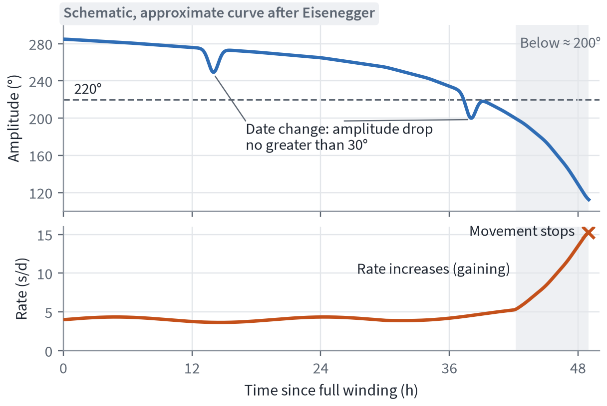
Amplitude and rate over the power reserve, schematic, roughly after Eisenegger's run-down diagram (Uhrenkonstruktion, p. 268), with the date change as in his first movement; the schematic does not show the steep fall in rate shortly before the watch stops. Dashed: 220°, the design amplitude after 24 hours.
But take care: the gaining at the end is not a rule. Eisenegger's run-down diagram is a measurement of three movements of IWC calibre 80110, an automatic movement with date, over the entire power reserve. The short accompanying text only explains what a run-down diagram is, and that the date change may cost at most 30° of amplitude; Eisenegger says nothing there about how the rate develops. Reading off the diagram, two of the three movements gain increasingly as the amplitude falls, from around +5 to a little over +14 and just under +9 seconds per day respectively. In the third, by contrast, below about 200° the rate falls from around +7 to +3 seconds per day: compared with full wind it is losing, even though it is still gaining. Shortly before stopping, the rate falls steeply in all three. The diagram therefore shows how these individual movements behaved.
At low amplitude, losing is usual, because the escapement itself makes the watch lose, and all the more so the lower the amplitude (Why the Swiss lever escapement makes a watch lose). That does not make Eisenegger's measurement wrong. Gaining is plausible if, for example, the hairspring rests against one side of the regulator pins or other additional effects act more strongly than the escapement. Eisenegger does not state in which position the measurements were made or how the hairspring is held.
Determining a movement's lift angle: the 180° method
The timing machine calculates with the lift angle you enter. If it is wrong, every displayed amplitude is wrong in the same proportion. If a movement really has 52° and the timing machine is set to 44°, it displays an actual 280° as 237°, and the movement appears weak. Conversely, a 6498 with its 44°, on a timing machine set to 52°, displays around 331° at a real 280° and falsely suggests a risk of rebanking.
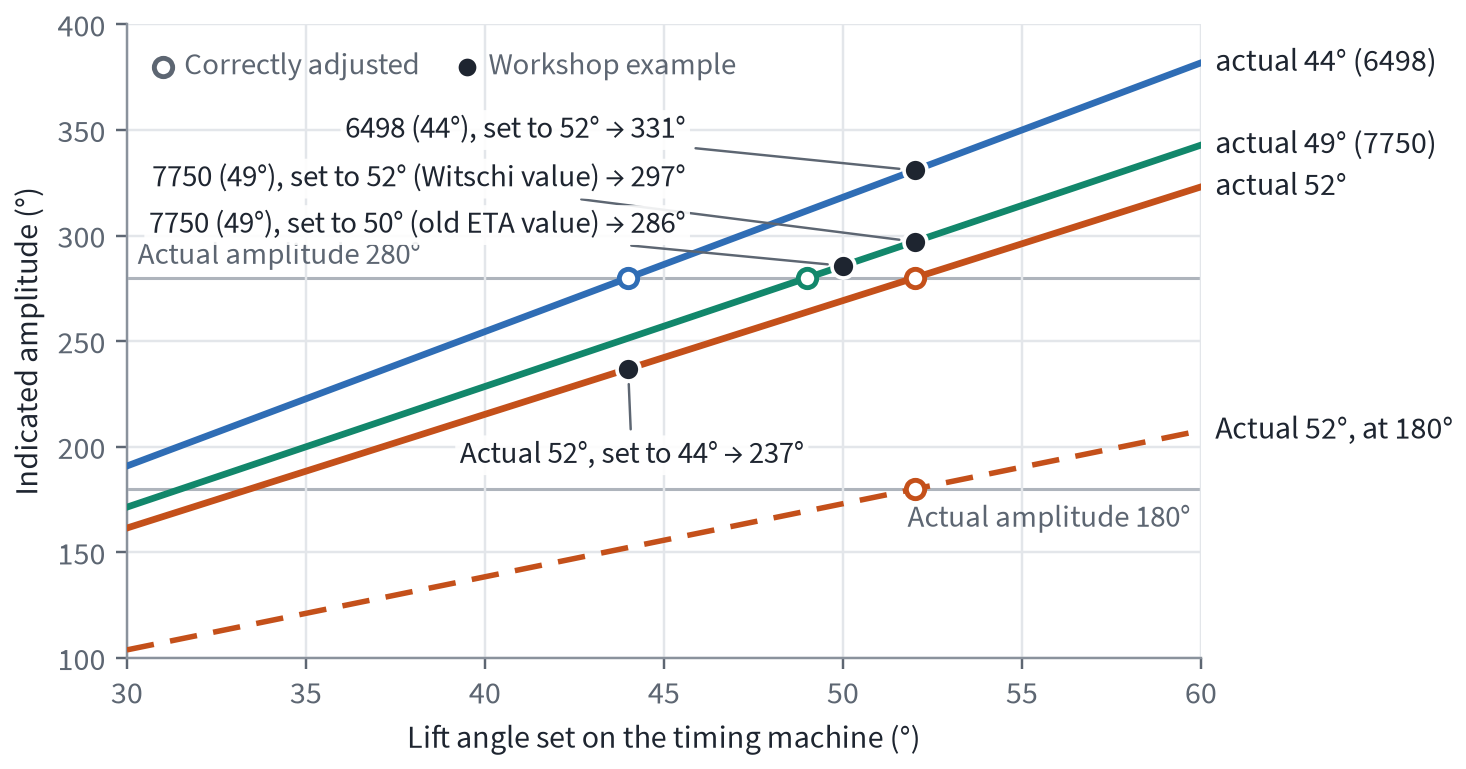
What the timing machine displays when the lift angle set on it is wrong.
If the value is missing, for example for an old or unknown calibre, it can be determined on the movement. I use a simple four-step method for this:
Mark a point on the balance rim.
Wind by hand until the point flashes at the same place on both the right and the left swing. The balance is then swinging exactly 180° by the watchmaking convention, that is, 180° to each side.
With a two-arm balance, no point is needed: wind until the arms coincide at the turning points. They also coincide at 90° and 270°, but then at right angles to the rest position; at 180° they lie in the same direction as at rest.
In exactly this state of wind, adjust the lift angle on the timing machine until it also displays 180°. The value set is the lift angle of this movement.
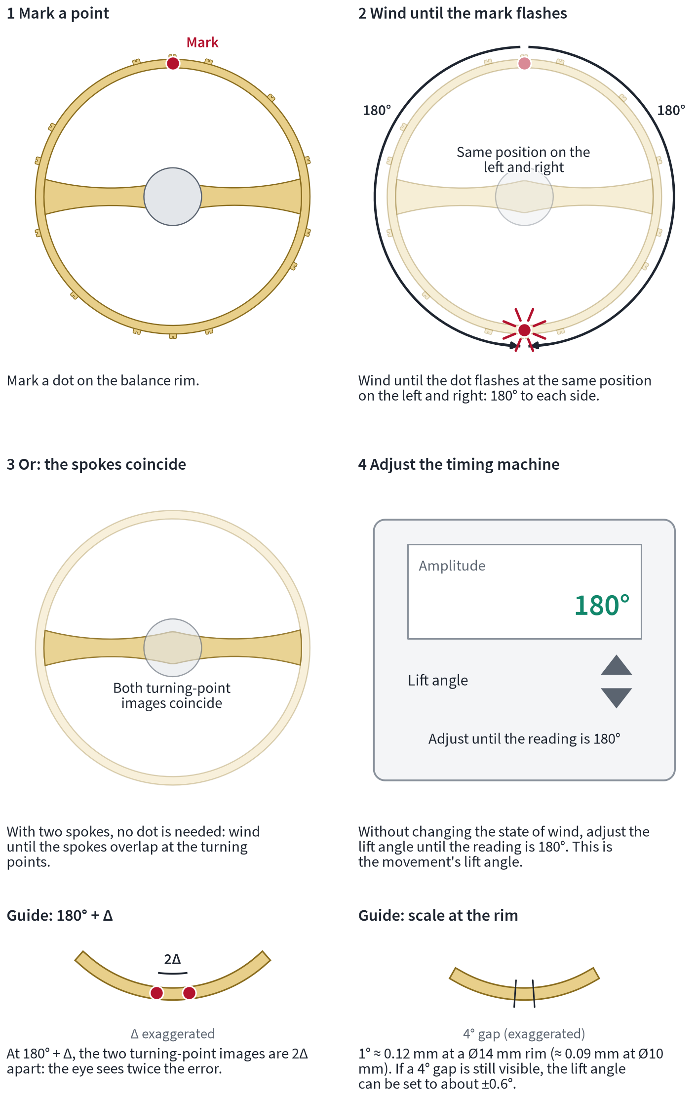
The 180° method in four steps. At 180° plus Δ, the turning-point images are 2Δ apart.
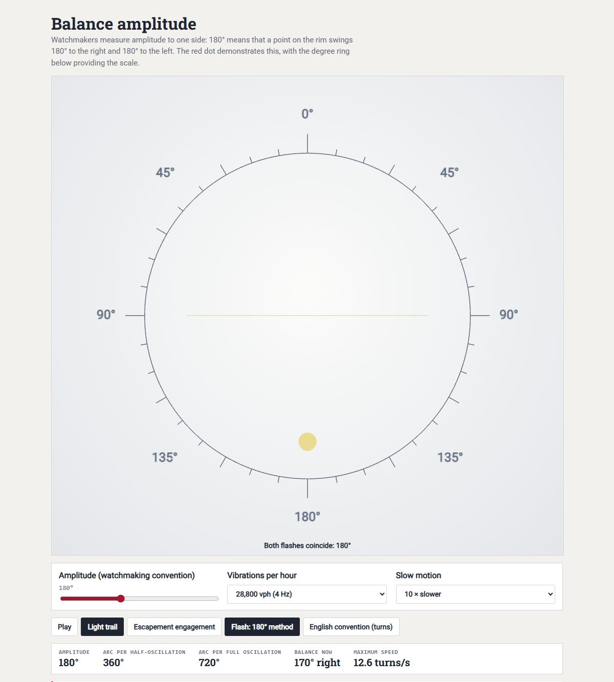 Open animation in a separate window
Try it out: at exactly 180°, the point flashes at the same place on the right and the left.
Why 180° in particular? Only at this amplitude do both turning points fall at the same place, and because the balance stands still there for a moment, the mark flashes visibly. The eye needs no scale; it only compares two images. If the balance swings a few degrees more or less, the two turning-point images are twice this deviation apart, so the eye sees double the error. On a rim 14 mm in diameter, one degree corresponds to around 0.12 mm, on a 10 mm rim to around 0.09 mm. If you can still make out a gap of 4°, you are within about ±0.6° for a lift angle of around 50°. A beat error hardly interferes, because the oscillation remains symmetrical about the hairspring's rest position.
The method does not appear in the Witschi manuals and training documents available to us. Its industrial counterpart is the WisioScope: it measures the amplitude optically, that is, with a light barrier, compares it with the beat sound and so outputs the “real lift angle” of the individual movement. Related workshop methods are older. Weger (1967) calls observing the images of the balance arms an equivalent way of determining the amplitude, and Reuer (1968) sets the amplitude by eye by winding slowly. Anyone who carries out dynamic poising at 180°, as the WOSTEP Feinregulierung course and the Würzburg master course specify, needs exactly this value set correctly.
For known calibres I take the value from the technical data; when I once checked it with the 180° method, it matched. I have also measured movements with 54°.
The calculation for the method is under The 180° method calculated, and the dynamics behind it under The lift angle in more detail.
Key point: If the mark flashes at the same place on the right and the left, the balance is swinging 180°. At that point, set the timing machine's lift angle so that it displays 180°.
Why the displayed amplitude is only an estimate
The timing machine does not measure an angle but a time, from the unlocking sound to the drop sound. From this it calculates the amplitude using three assumptions: the balance oscillates like a free pendulum, that is, along a sine curve; the lift angle lies symmetrically about the dead point; and in the measured time the balance sweeps through exactly the lift angle entered. The shorter the time, the faster the balance passes through the dead point and the greater the amplitude must be. At 4 Hz and 52°, 280° corresponds to around 7.4 ms and 180° to around 11.5 ms; even a shift of 0.1 ms changes the reading at 280° by almost 4°. Conventional timing machines therefore estimate the amplitude; they do not calculate the lift angle but need it as an input. Only instruments with optical measurement determine it themselves.
Ten reasons why the reading is never entirely accurate, explained and quantified under The lift angle in more detail:
lift angle only “typical” or out of date
tolerances in the movement
the escapement shifts the sounds (banking, clearances, drop, run to the banking)
sinusoidal oscillation only assumed: the balance is braked during unlocking and driven during impulse
sound detection: start and end depend on the gain
dynamics: rebound, delayed impulse
position: bearing play shifts the centreline in vertical positions
instrument: timing machines represent the same time differently
environment: temperature, air pressure, condition of the oil
average over many beats instead of an instantaneous value
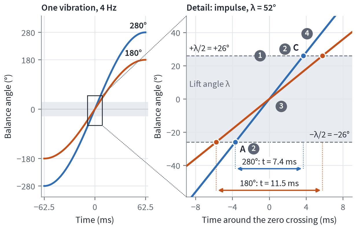
The greater the amplitude, the shorter the time in which the balance passes through the lift angle.
In practice, this means that the values on the timing machine are not absolutely exact. Calibrated with the 180° method, the reading is correct at 180° and good in its vicinity; at 280° a small residual error remains (The 180° method calculated).
Key point: The timing machine measures a time and estimates the amplitude from it. Comparing is more reliable than reading off.
Escapement trace patterns
The timing machine's trace, the row of dots it plots beat by beat, reveals many escapement faults before the movement is even opened. We generated the sample patterns here ourselves; they are not manufacturer images:
Pattern | What you see | Suspicion |
|---|---|---|
in order | a steady, straight line | – |
out of beat | clear double line: two straight, parallel lines a fixed distance apart | impulse pin not on the centreline at the dead point |
guard pin rubs | no straight lines: scattered dots (“snow”), fluctuating rate trace | guard pin clearance too small |
wave in time with the escape wheel | regular wave, every 6 s with 15 teeth and 18,000 vph, every 5 s with 20 teeth and 28,800 vph | escape wheel out of round |
outliers | isolated offset dots, once per revolution of the escape wheel | damaged tooth |
rebanking | jumps, in extreme cases a “snowstorm” | amplitude too high |
endshake | unsteady, irregular line | endshake of pallet fork or balance too large |
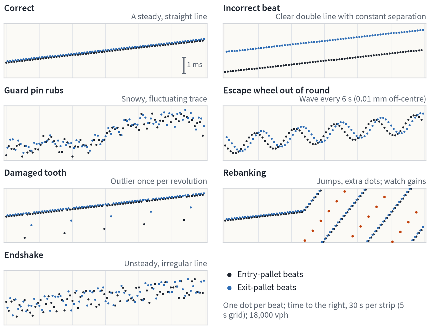
Sample traces, generated by us. Schematic.
It becomes even more precise in scope mode, that is, the view of a single beat, in which the timing machine draws the loudness profile of the three bursts as an envelope. If the lock is too light, the unlocking and impulse sounds almost merge; if it is too heavy, all three bursts lie far apart. For “unlocking too strong”, Witschi shows a pattern of its own: the first two bursts are strong and lie close together. Witschi gives no cause for this; it is not to be confused with a lock that is too deep, which pulls the bursts apart. If the guard pin rubs, small extra bursts appear; if the horns touch the impulse pin, the third burst rings on for a long time. If a tooth drops directly onto the impulse face, there are only two bursts. With rebanking, there is an extra burst before the first and another after the third, and with low amplitude the interval from the first to the third burst becomes large.
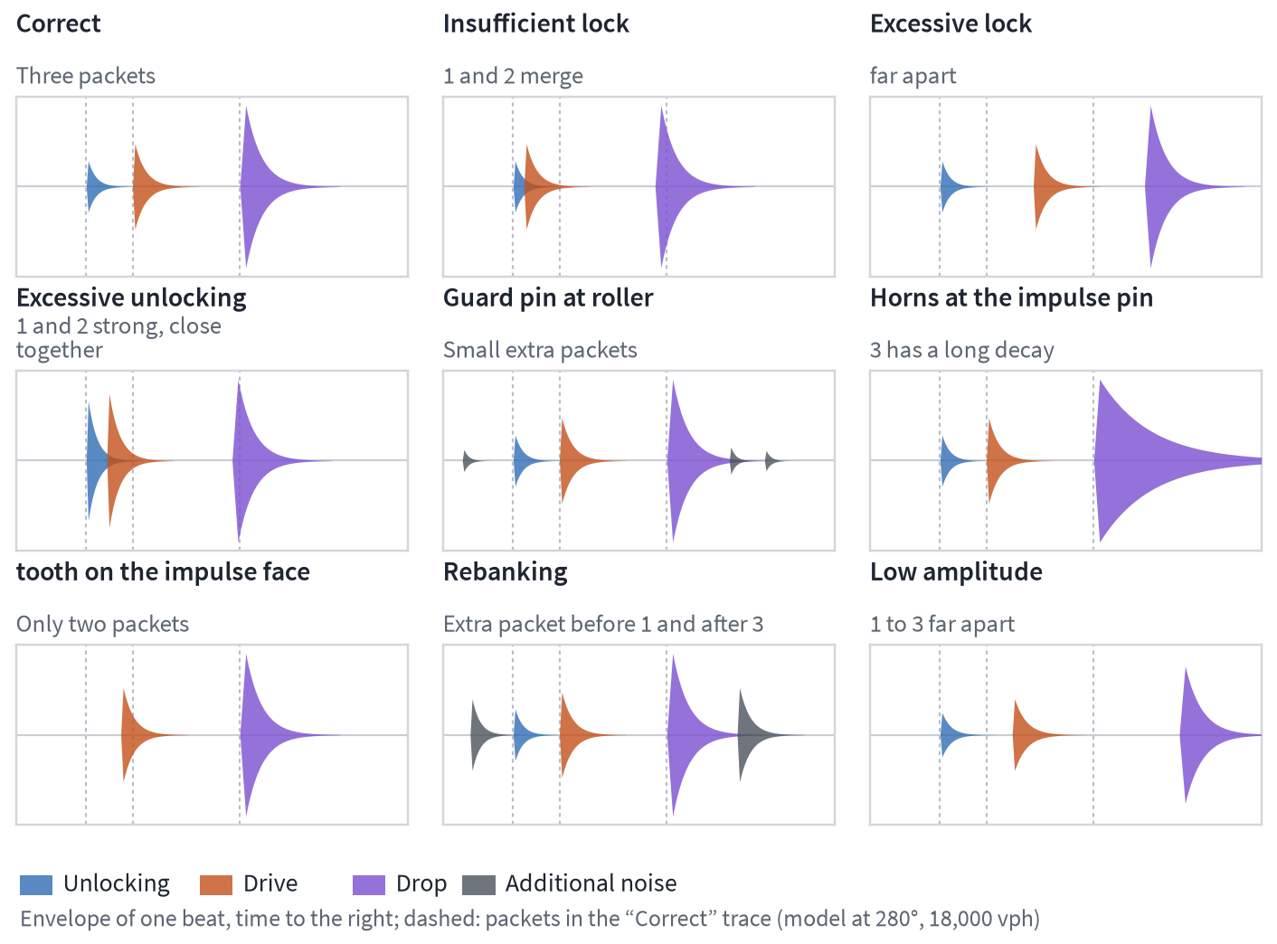
Scope patterns drawn by us from the manufacturer's descriptions. Schematic.
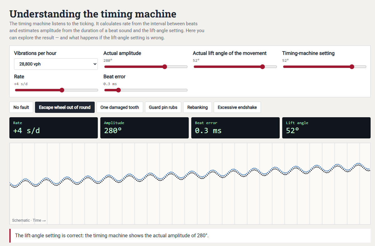 Open animation in a separate window
The timing machine simulator: choose a fault pattern and see which trace it produces. Schematic.
Three old workshop tricks: if a second row of dots appears to the left of the first when the gain is turned up, the unlocking is too heavy (Reuer). According to Weger, an impulse pin offset by 2° gives around 2 ms at 18,000 vph; Weger counts the whole difference between the two half-oscillations, whereas today's timing machines display half of it, so around 1 ms at 250° (formula under Beat error in milliseconds and in degrees). And Weger allows a “matchstick's width” of beat error on the strip, that is, less than 1 ms.
On the trace, a beat error and a rubbing guard pin cannot be confused. A beat error gives an absolutely clear double line: two straight, parallel lines. A rubbing guard pin always gives some “snow”, that is, scattered dots, and a fluctuating rate trace without straight lines. In that case, check the guard pin clearance.
From finding to suspicion
During a repair at the bench, the search begins with the finding. The table leads from the symptom or trace pattern to the first suspects, to the appropriate check in the chapter Checks at the bench and to the profile in the chapter Escapement faults:
Demagnetise before checking!
Finding | First suspects | Check | Profile |
|---|---|---|---|
runs lying flat, stops on the wrist | guard pin or horn clearance greater than the lock, lock too small | ||
stops in the morning, does not start by itself | unlocking too heavy, lock or draw too great, mainspring weak | ||
knocks and gains heavily | rebanking due to excessive amplitude | Amplitude dial up, fully wound | |
amplitude low | lock too deep, fork clearance too large, oil, going train | ||
clear double line | out of beat | ||
snow, fluctuating rate trace without straight lines | guard pin rubs | ||
wave in time with the escape wheel | escape wheel out of round (older watches), lock varies from tooth to tooth | ||
outliers once per revolution of the escape wheel | damaged tooth | ||
outliers in one position | endshake, pivots, slanting banking pin | ||
extraneous noise | guard pin rubs the roller, horn touches the impulse pin | ||
unlocking and impulse sounds merged | lock too light | ||
only two bursts | tooth drops onto the impulse face | ||
small extra bursts around the beat | guard pin against the roller | ||
extra burst before the first and after the third burst, plus heavy gaining | rebanking | Amplitude dial up, fully wound | |
row of dots on the left when the gain is turned up | unlocking too heavy |
Key point: Measure first! The timing machine sometimes tells you where to look and can make fault-finding easier.
Checks at the bench
Each check here follows the same pattern: what you check, in which position and with which manipulation, which target value applies, which finding points to which cause, where the correction is described, and what value our model has according to the workshop rule. The model before adjustment serves only as a counter-example.
The order runs from the inside out: from the impulse pin in the fork, via the escape wheel and pallet stones, to the horns, guard pin and beat. Other schools check in a different order; the comparison is shown in Two schools: the order of checking and adjusting. Where a check belongs to a phase, “View the phase” leads to the phase animation; “View the manipulation” opens the test bench.
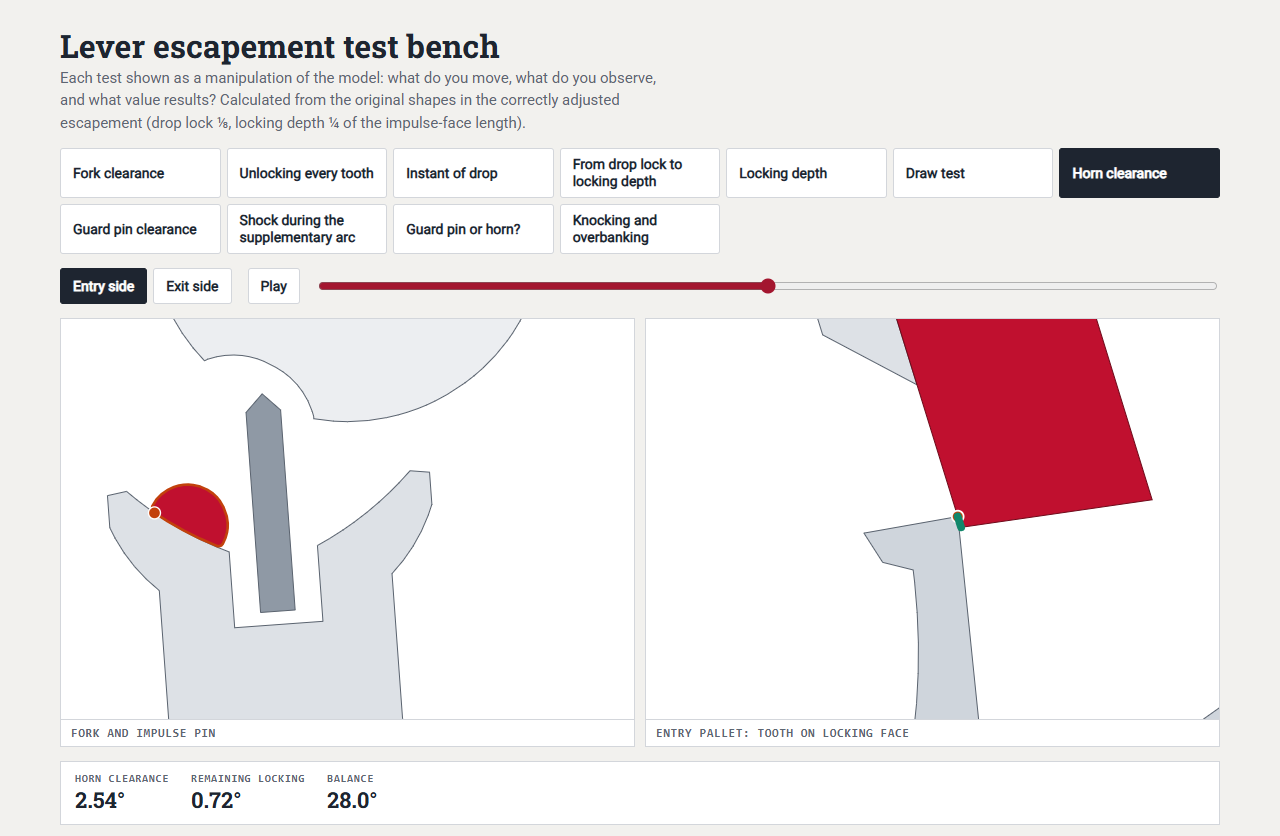 Open animation in a separate window
Test bench: choose a check, and the position and manipulation run as an animation; the detail beside it shows the residual lock at the tooth, with the measured values below.
Before checking: basic rule, tools, condition, endshakes
On one point all schools agree: first everything is checked and noted, then you change one thing, and then you check everything again. Anyone who moves a pallet stone straight after the first finding alters values they do not yet even know.
During my training I checked every escapement in the same order, even before the movement was dismantled: drop lock and depth of lock under the microscope or with a 10× loupe while the balance was still fitted, then draw, guard pin, horns and the firm seating of the pallet stones, and after that the endshakes.
As tools, a microscope or 10× loupe, a fine oiler, pegwood and soft brass tweezers are enough. The mainspring is wound only slightly (Bossart), but not too little: the smaller the force, the greater the effect of pivot play (Pforzheim course notes). The instant of drop and the clearances are checked with the balance and hairspring fitted.
Before the functions comes the condition of the components:
banking pins straight and secure,
pallet stones flat, flush with the top of the pallet fork body, firmly set in shellac, without cracks or chips,
guard pin straight, centred between the horns, tip undamaged,
horn tips and fork slot free of notches and burrs,
impulse pin secure, upright and free of cracks,
pivots and jewels clean and undamaged,
escape wheel checked for truth in the round and in the flat, that is, neither out of round nor wobbling.
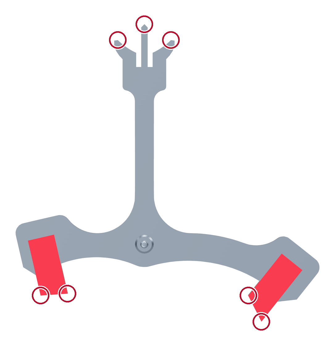
Where a pallet fork can wear when there are escapement faults: horn tips, pallet stone edges, running surfaces and guard pin tip. Look at these spots under the loupe before every check. Damage is a sign of malfunctions.
The endshakes, that is, the axial play of the staffs between the jewels, follow the manufacturer's specification. The sources give different ranges:
Source | Escape wheel | Pallet fork | Balance |
|---|---|---|---|
Pforzheim course notes (training, 2010) | 0.01–0.02 mm | 0.01–0.02 mm | 0.01 mm |
Bulova course (c. 1945) | 0.02–0.04 mm | 0.02–0.04 mm | 0.02–0.04 mm |
Rolex 3135 (manufacturer's specification) | 0.02–0.06 mm | 0.01–0.04 mm | 0.02–0.03 mm |
For radial pivot play, Berner's Merkblatt für die Regulierung gives 0.005 mm at the pallet fork and 0.0075 mm at the balance. Added to this are the height relationships, labelled a to g in Theorie der Uhrmacherei:
a: The teeth run roughly centrally on the pallet stones.
b: The guard pin, or its block, has freedom from the mainplate.
c: The top of the pallet fork has freedom from the pallet bridge.
d: The guard pin lies at the height of the safety roller.
e: The fork has freedom from the underside of the large roller.
f: The small roller has freedom from the balance jewel setting.
g: The impulse pin has freedom from the guard pin.
If a freedom is missing, you move the jewels of the escape wheel or pallet fork, or the balance jewel setting; if necessary, the Pforzheim course notes reposition the pallet fork on its staff.
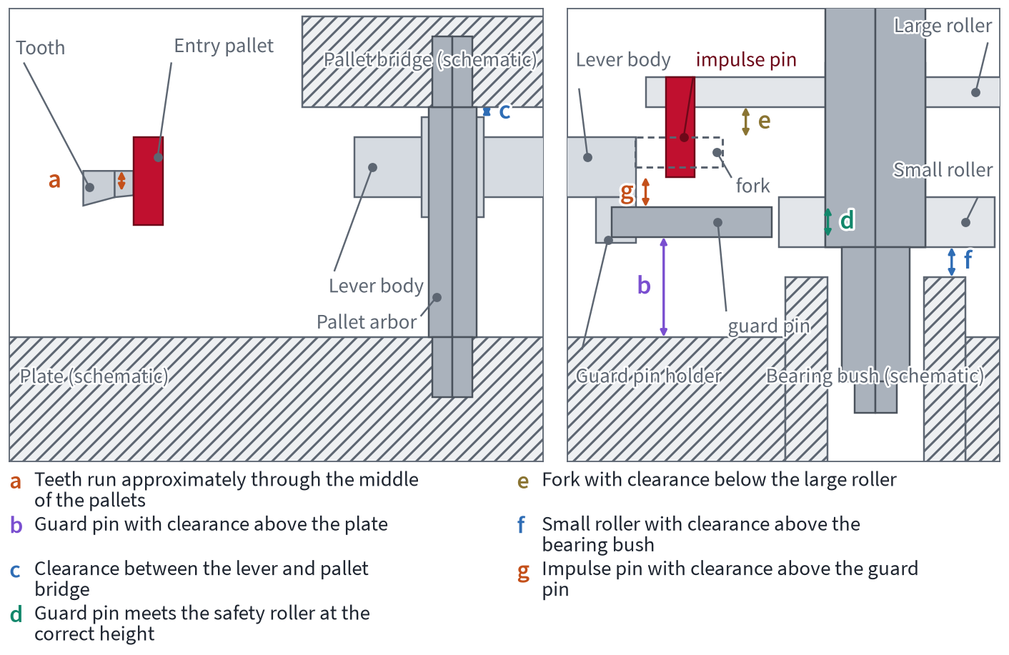
Height relationships a to g in a side section of our model. These freedoms are checked before any of the functions.
The following table assigns each check to its phase, its means of adjustment and the matching fault pattern under Escapement faults: from symptom to cause.
Check | Phase | Means of adjustment | Fault pattern |
|---|---|---|---|
dead point | impulse pin, fork | ||
1 unlocking | pallet stones, escape wheel | ||
3 drop | pallet stones | ||
4 run to the banking | pallet stones, banking pins | ||
4 run to the banking | cleaning, escape wheel, endshake | ||
5 locking and supplementary arc | banking pins, horns, impulse pin | ||
5 locking and supplementary arc | guard pin, last | ||
dead point | hairspring collet, stud carrier |
All checks on one page: Printable check sheet (PDF).
Key point: First check everything, then change one thing, then check everything again.
Fork clearance and depth of engagement
Fork clearance is the smallest clearance in the escapement. It must nevertheless be perceptible, otherwise the impulse pin binds in the slot.
Position and manipulation: let down the mainspring and bring the balance to the dead point, so that the impulse pin lies on the line between balance and pallet fork. Then hold the balance with your thumb (finger cot!) and use the oiler to move the pallet fork back and forth at one pallet stone: the impulse pin must touch both flanks (Pforzheim course notes).
But take care: checking in the centre position alone is not enough. Bossart also checks at the instant of unlocking, because the play changes with the position.
Target value: perceptible on both sides, but without free travel. For slot width minus jewel width, the Bulova course gives 0.01 mm for small movements up to 0.03 mm for large pocket watches. Any free travel costs energy: if the pallet fork travels 1° freely before the flank reaches the impulse pin, the balance loses around 3° of lift angle with a lever ratio of 3 : 1. Then there is wear, because at 18,000 vph the flanks of the slot take 36,000 blows an hour (Bossart).
Finding and cause: too much fork clearance comes from a worn slot, an impulse pin that is too small, worn, loose or set crooked, or from pivot play. The remedy is a wider impulse pin (Jendritzki); Bossart closes up a slot that has opened too far and then resets the horn clearance. If the impulse pin binds, the slot is too narrow, and Theorie der Uhrmacherei recommends a new pallet fork. In fact, you should not try to imitate Bossart's method, because high-quality pallet forks made of hardened steel break and cannot be bent. Jendritzki's method, together with reworking the fork slot, is better.
Our model: 0.48° at the pallet fork. Recalculated, this is around 0.026 mm of play at the impulse pin, 3.05 mm from the pallet centre, in the upper part of the Bulova range, and around 1.5° of free travel at the balance.
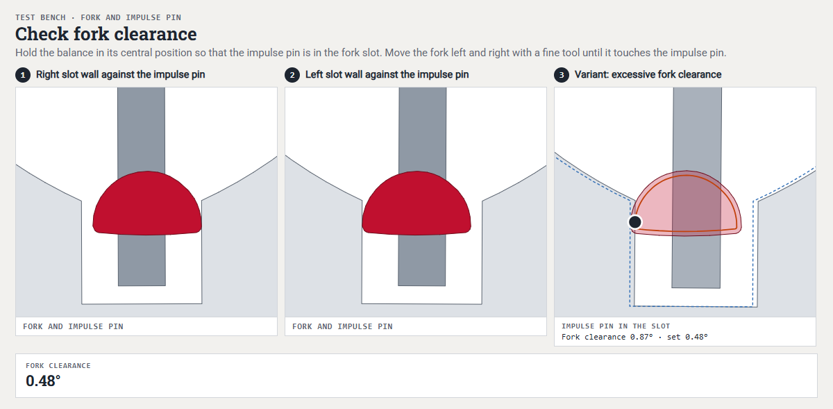 Open animation in a separate window
Checking fork clearance: the fork swings back and forth around the stationary impulse pin. The fault atlas shows too much fork clearance, with an impulse pin 0.01 mm smaller, as a red deviation over the original shape.
Depth of engagement, that is, how far the path of the impulse pin and the fork corner overlap: it must be greater than the horn clearance (Würzburg master course). If it is too slight, the impulse pin can strike the fork corner after a shock instead of sliding into the slot. This can happen particularly in modern watches with shock protection, because the balance can move sideways and the impulse pin could be lifted out of the fork slot if it is too shallow.
Our model shows some interesting relationships. The far fork corner, the corner of the flank that the returning impulse pin has to push, is engaged by the impulse pin to a depth of 0.045 mm (entry) and 0.041 mm (exit) with the pallet fork against the banking pin. As lever angles, these are 2.27° and 2.04°. Before adjustment they were 2.71° and 3.20°, because every degree by which you open a banking pin takes as much from the depth of engagement as it gives to the horn clearance. The near fork corner, which the impulse pin could strike after a shock, only projects into its path at 2.68° and 2.91° respectively of lever travel towards the centre, just over the horn clearance. What matters is safety: when the guard pin is in the passing hollow, the horn catches the impulse pin after a shock, first with the horn tip, then with the horn curve, never with the fork corner. In the process, at least 0.65° and 0.54° of lock respectively remain, no tooth reaches the impulse face, and as long as the pallet fork lies against the horn, the impulse pin engages the far fork corner even more deeply, 0.074 mm.
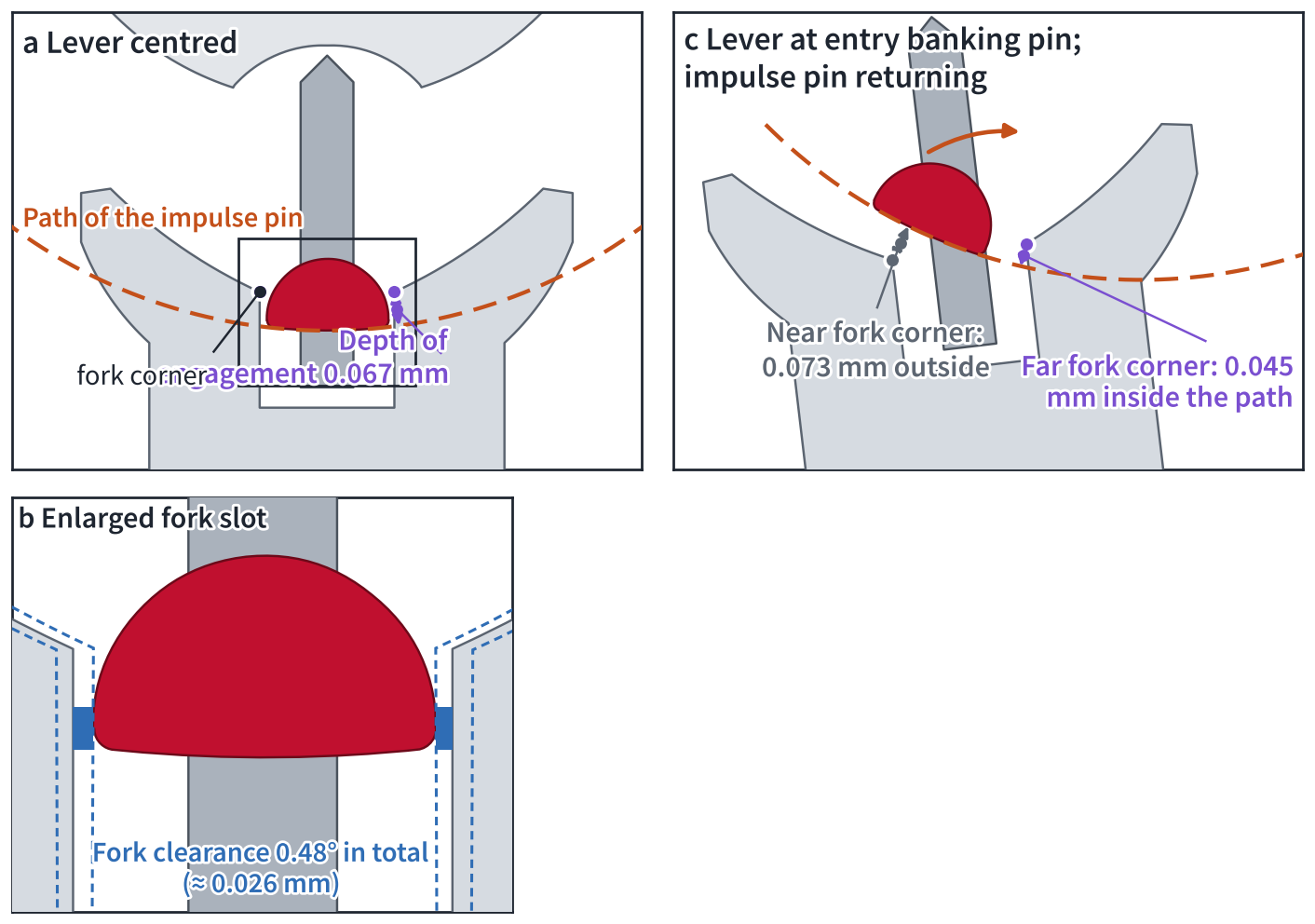
Fork corner and path of the impulse pin: depth of engagement and fork clearance dimensioned, together with the far and near fork corners with the pallet fork against the banking pin.
Unlocking every tooth
Phase 1 · unlocking · View the phase · View the manipulation
This test shows whether every tooth drops freely at both pallets. Apply only a little force to the going train and unlock the lever tooth by tooth via the balance, using your thumb (finger cots!), until the escape wheel has gone round once; with 15 teeth that makes 30 unlockings (Pforzheim course notes). It works just as well without the balance: if you tap the end of the fork, the lever must spring quickly to the other side and release a tooth, and no pallet may stay resting on a tooth's locking corner (Smith). Slow unlocking is better still, guiding the lever arm with brass tweezers, because this lets you compare the points at which the teeth land. Guiding by hand has the advantage that you can also lift the lever slightly within its bearing play, so you also uncover problems caused by leaning banking pins – with leaning banking pins that are further open at the top than at the bottom (with regard to endshake), a tight escapement may well be set at one height in such a way that it could jam if the watch receives a hard shock at the wrong moment.
Finding and cause: if the pallet fork tilts during the drop or a tooth catches, the position of the pallets is wrong, or the escape wheel has uneven pitch or runs out of round. If the pallets are to blame, they are moved (see Moving the pallet stones and adjusting the banking). An escape wheel that is out of round is replaced.
Our model unlocks securely at all 15 teeth. Even here, however, the teeth are not completely identical: the model's escape wheel is slightly oval (±2 µm) and has a pitch error of ±0.03°. This is why the values scatter over one revolution of the escape wheel even on the adjusted model. The depth of lock lies between 3.24° and 3.38° on entry and between 3.28° and 3.42° on exit, and the drop varies by a good 0.1° at the escape wheel. The values we give elsewhere (3.26°/3.36°) apply to one particular pairing of teeth and lie within these ranges. How an escape wheel that is out of round makes the lock wander over one revolution is shown in Shape and position errors on the escape wheel, pallet fork, fork and pallets.
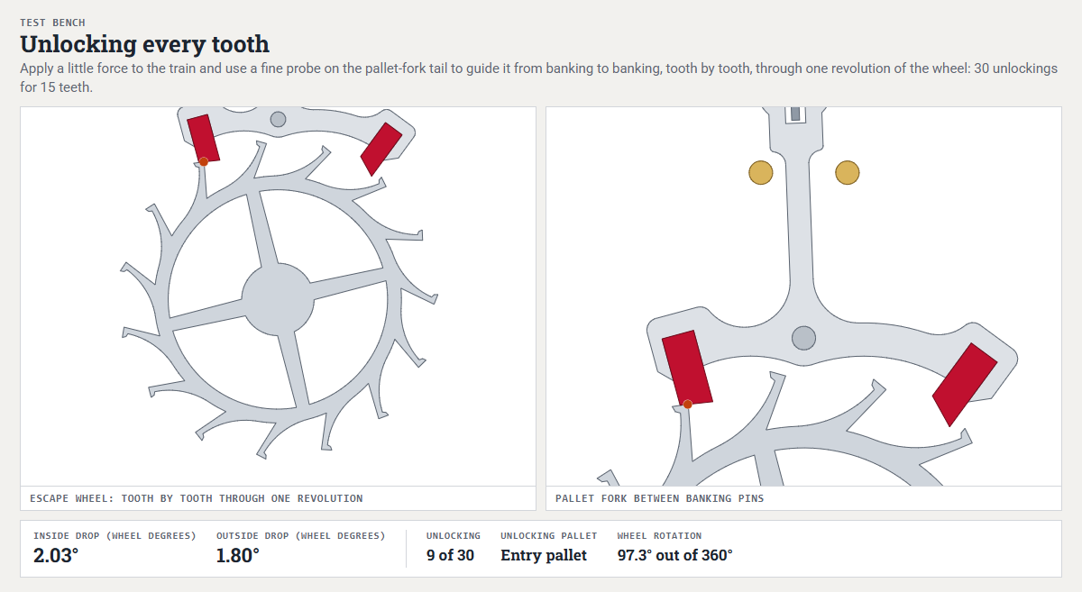 Open animation in a separate window
Unlocking every tooth on the test bench: the pallet fork is unlocked via its lever arm, tooth by tooth, over one revolution of the escape wheel.
Stopping at the instant of drop: drop-lock point, drop, fork play
Phase 3 · drop · View the phase · View the manipulation
One manipulation gives three findings. With only a little force on the going train, guide the balance slowly with your thumb (finger cot!), follow the tooth across the impulse face and stop exactly at the instant it drops. In this position the lever arm is not yet resting against the banking pin, and you can read off all three values. The Bulova course uses the same check with fixed banking pins.
a) Drop-lock point: on every tooth and at both pallets it must lie on the locking face, and no tooth may drop onto the impulse face (Pforzheim question set). According to the workshop rule, the drop lock is ⅛ of the impulse face.
b) Drop: check the inside and outside drop, in the least favourable position, in which a tooth's let-off corner faces the pallet's let-off corner. Both should be roughly equal: around 1½° at the escape wheel according to Bossart, 1–3° according to Jendritzki. A check by hand lacks the recoil that the escape wheel also makes during unlocking when the watch is running. When running, the drop is therefore even smaller than it appears by hand. With play in the pivots, Bossart therefore considers 0.02 mm of drop, measured at the circumference of the escape wheel, too little.
c) Fork play at the instant of drop: the fork can still be moved back and forth a little until a fork corner rests against the front or back of the impulse pin, without the lever arm touching a banking pin. The play must be equal on both sides, because only then does the lever swing equally far beyond the centreline on each side (Bulova course). The pallet-stone rule is based on this finding; see Fork play at the instant of drop and the pallet-stone rule. In practice, we guide the balance by hand and gently wiggle the lever with a long oiler at a point where it cannot leave scratches, for example on top of the ruby pallet. We also check guard pin clearance and horn clearance this way.
Our model: the drop lock is 1.48° on entry and 1.68° on exit, both about ⅛ of the impulse face. The inside drop is 2.03° and the outside drop 1.80° at the escape wheel, slightly more than Bossart's 1½°. Fork play at the instant of drop is 0.90° for the drop onto the entry pallet and 1.20° for the drop onto the exit pallet. The model therefore misses the target of “equal on both sides” by 0.30°. At the instant of drop, the lever stands 4.9° and 5.2° respectively past the centre. This can only be changed via the opposite pallet, because the banking pins have no influence on it.
If a tooth strikes the impulse face, the drop lock is too small. Causes and remedies are under Borderline cases: when the tooth drops onto the impulse face. For adjustable banking pins there is an old method, “banking to the drop”. It is described, with instructions, in the box under Adjusting the banking.
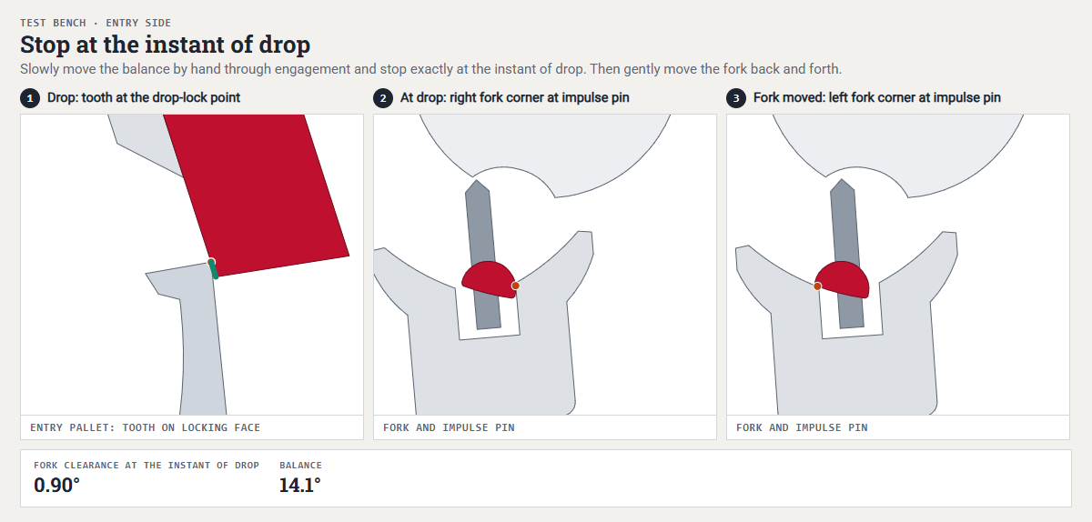 Open animation in a separate window
Stopped at the instant of drop: drop lock and fork play on either side of the impulse pin.
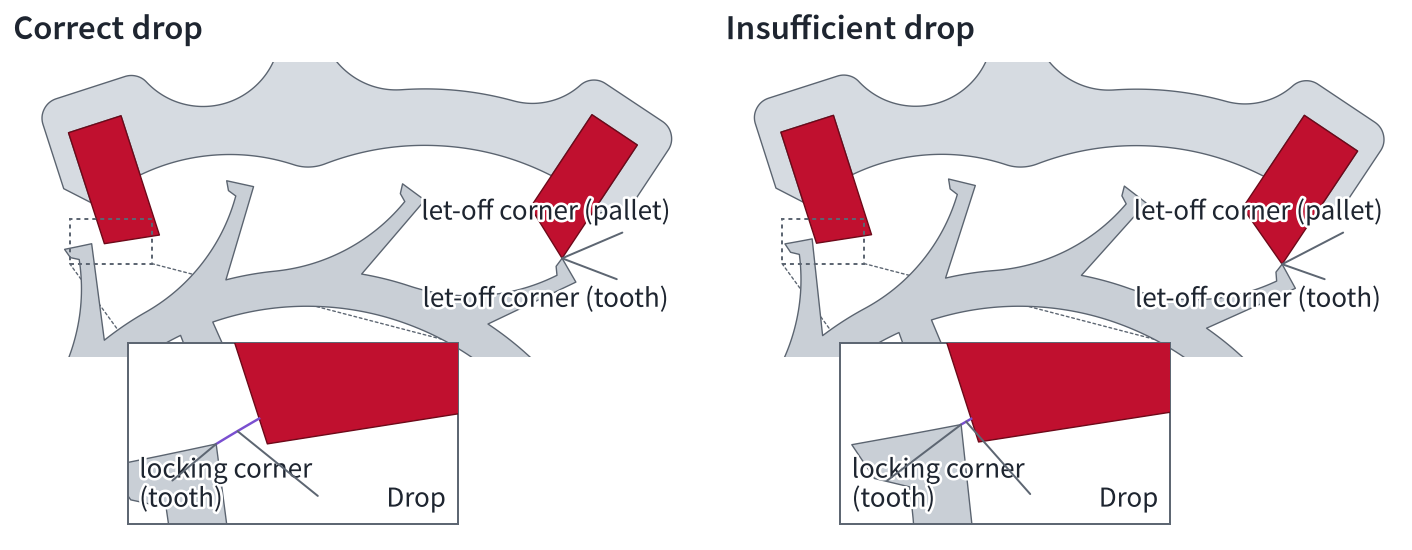
Left, a good drop; right, one that is too small. If the drop is small, an unfavourable combination of clearances and elasticity of the parts can prevent the tooth from dropping. The escapement then hesitates for milliseconds, eats up energy and wears.
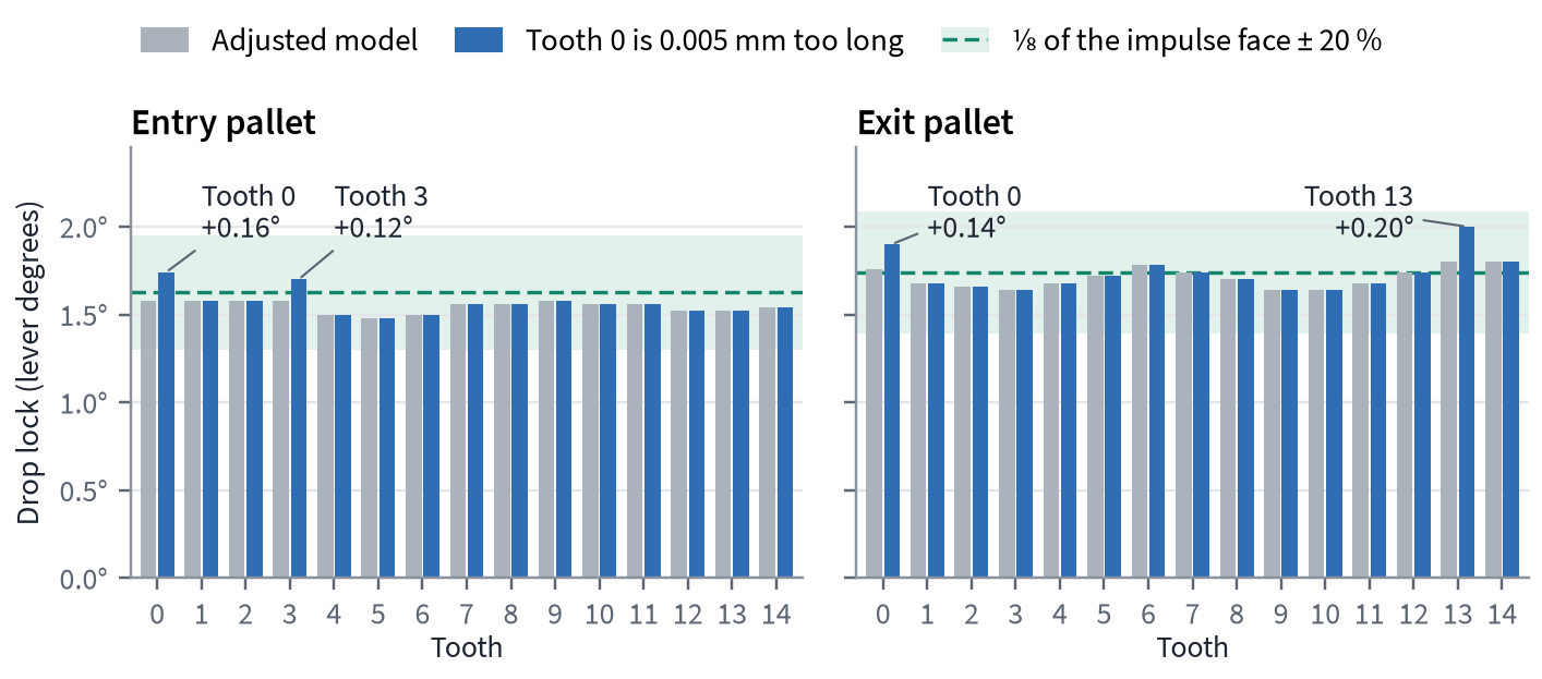
Drop lock per tooth over one revolution of the escape wheel. If tooth 0 is 0.005 mm too long, its drop lock increases by around 0.15° at both pallets. In addition, the tooth that drops at the instant the long tooth leaves the other pallet also lands deeper. This is why you check every tooth and never set the escapement as tight as possible.
Depth of lock and run to the banking
Phase 4 · run to the banking · View the phase · View the manipulation
Depth of lock and run to the banking are checked in one manipulation, at both pallets and over a full revolution of the escape wheel.
Manipulation: from the position at the instant of drop, turn the balance further away from the centreline (Pforzheim course notes). Draw pulls the lever to the banking pin, and the tooth slides a little deeper onto the locking face. This travel of the lever is the run to the banking. Then guide the balance slowly back, and the impulse pin turns the lever away from the banking pin until the tooth's locking corner stands at the pallet's locking corner. The distance through which the lever turns in doing so is the depth of lock. With the balance fitted, the depth of lock cannot be checked with the oiler alone, because before the tooth reaches the pallet's locking corner, the guard pin comes up against the safety roller or, near the fork slot, the horn comes up against the impulse pin. So you must either grip the lever carefully by its arm and guide it, or, better, work through the fitted balance as described.
Target value: the Pforzheim course notes give three golden rules. All teeth drop securely onto the lock, the depth of lock is equal at both pallets, and it is no deeper than necessary, on average ¼ of the impulse face. This quarter, measured from the pallet's locking corner to its let-off corner, is also our workshop rule. It is checked by eye, ideally under the microscope. If no microscope is available, with a 10× loupe. It is not measured in degrees, because angles this small cannot be seen, whereas a length on the pallet is easy to estimate (Drop-lock point, depth of lock, run to the banking). Whether the run to the banking should be as small as possible is an old point of dispute; see What really happens: the dynamics behind the slow motion.
Finding and cause: an unequal depth of lock or an unequal run to the banking points to a displaced pallet or a leaning banking pin (Pforzheim question set). If the depth of lock wanders from tooth to tooth, the escape wheel is running out of round. The correction is under Moving the pallet stones and adjusting the banking.
Here in the 3D model: the depth of lock is 3.26° on entry and 3.36° on exit, i.e. ¼ of the impulse face. The run to the banking is 1.78° and 1.68°, about half the depth of lock. Before adjustment, the model showed the finding of the exercise from the start of Part 2: the depth of lock was 2.98°/2.34° and the run to the banking 1.22° on entry, but only 0.34° on exit. The solution is under The exercise solved: which pallet, which direction, how much.
Key point: drop lock plus run to the banking gives the depth of lock.
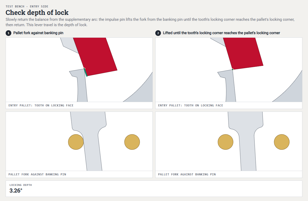 Open animation in a separate window
Checking the depth of lock: the balance is guided slowly back, and the impulse pin turns the lever away from the banking pin until the tooth's locking corner stands at the pallet's locking corner.
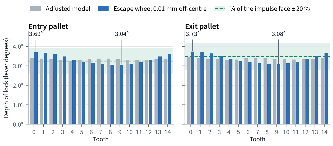
Depth of lock per tooth over one revolution of the escape wheel: grey, the adjusted model; blue, the same model with an escape wheel running 0.01 mm off centre. The depth of lock then wanders from tooth to tooth as a wave of ±0.3°. The line marks ¼ of the impulse face, the band ±20%.
Draw test
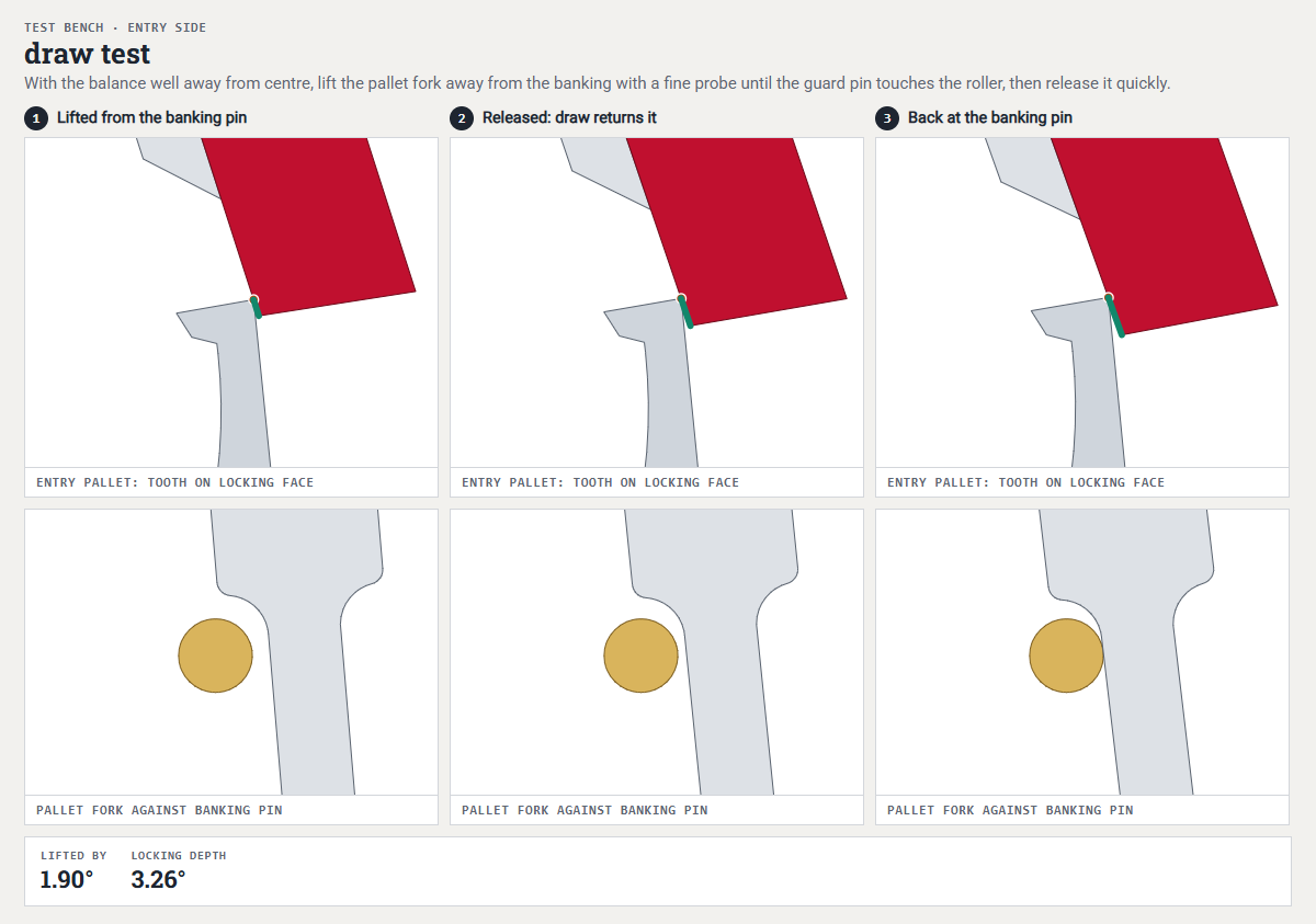
At the bench, draw is not measured but checked (Pforzheim course notes). To do this, use the oiler to lift the lever slightly away from the banking pin, within the lock, and release it. At both pallets it must spring back to the banking pin immediately.
The Bulova course makes the test stricter. Press the guard pin against the safety roller, watching the lock as you do so, and release the fork quickly. Draw must immediately pull the guard pin away from the safety roller and bring the lever arm to rest against the banking pin. This checks draw from the furthest position the guard pin allows during running. This matters above all on exit, because there draw weakens towards the pallet's locking corner (Bossart). On the model, the draw angle there falls from 15.5° with the lever at the banking pin to 12.1° at the pallet's locking corner.
Finding and cause: if the lever returns sluggishly or not at all, the pallets or teeth are dirty or rough, the teeth's locking corners are rounded, or the lever's endshake is too large. According to Helwig, the cause is usually the locking corners of the escape-wheel teeth, and then only a new escape wheel helps. The fact that the escape wheel turns back slightly as the lever is lifted does not on its own prove reliable draw, because only the lever springing back shows whether draw overcomes friction.
The draw angle itself is measured with a crosshair microscope; see Draw in more detail: effective draw, friction angle, measurement.
Key point: from any position within the lock, the lever must return to the banking pin by itself. Otherwise the guard pin could rub against the balance's roller.
 Open animation in a separate window
Draw test as in the Bulova course: the lever is lifted until the guard pin rests against the safety roller, and springs back to the banking pin when released. The entry and exit sides can be switched.
Horn clearance
Phase 5 · locking and supplementary arc · View the phase · View the manipulation
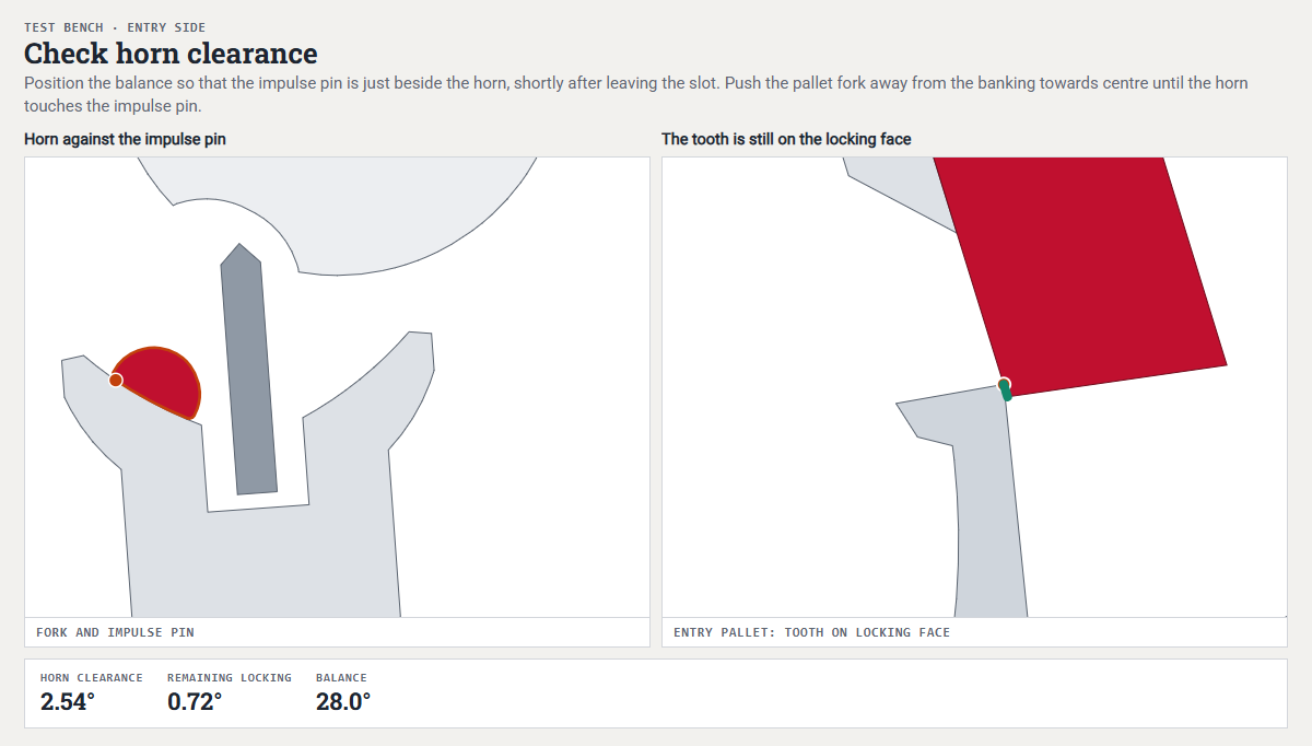
What is checked is the distance through which the lever can be turned from the banking pin until a horn touches the impulse pin. As long as the guard pin is in the passing hollow of the safety roller, the horns secure the lever, because otherwise a shock shortly before unlocking could lead to overbanking.
Position and manipulation: turn the balance far enough for the impulse pin to stand just outside the fork slot, in front of the horn, i.e. by about half the lift angle plus 10°. The Pforzheim course notes give 35–40° from the dead point for this, which suits movements with a lift angle of around 50°. For our model, with a lift angle of around 35°, it is about 27–28°. Because the engagement is not exactly centred on the dead point, it is more accurate to take, for each side, the point at which the impulse pin leaves the fork and add 7–10°. In the model it leaves the fork at 19.9° and 20.4° respectively, so the checking position is around 28°. Then move the lever away from the banking pin until the horn rests against the impulse pin, and repeat this along the whole length of the horn and on both horns. While doing so, watch the tooth on the locking face.
Target value: horn clearance must be safely smaller than the depth of lock, so that the tooth is still on the lock when the horn is in contact (Pforzheim course notes, Bossart). But it must be at least as large as the run to the banking, because the fast-moving impulse pin leaves the fork before the lever reaches the banking pin, and would otherwise brush the horn (Bossart). It is smallest at the start of the horn and increases outwards, and it should be equal on both sides (Pforzheim course notes). On the inside it is at most as large as the guard pin clearance, and larger at the outer end of the horn (Bossart, Theorie der Uhrmacherei). Theorie der Uhrmacherei puts the mean horn clearance at about half the depth of lock. For me, function is what counts: in no position along the horn may a tooth reach the impulse face, and a small safety margin must remain. That is why I never measure horn clearance at just one point (Depth of engagement).
Finding and cause: if horn clearance is too large, a shock brings the tooth onto the impulse face. The horn then presses against the impulse pin and brakes the balance (Runs lying flat, stops on the wrist: wedging). If the escapement already jams during the check, there is too little lock. If the impulse pin rubs on the horn despite correct horn clearance, the pallet's locking corner is often rounded (Bossart). If the play changes as the impulse pin passes the horn, the impulse pin is set at an angle. Horn clearance must not be confused with fork play at the instant of drop, which Brinkmann also calls horn clearance (Terms that are often confused). The correction is under Adjusting the guard pin and horns.
Our 3D model: horn clearance is 2.58° on entry and 2.79° on exit, measured at a balance position of 23°, i.e. shortly after the impulse pin has left the fork. At 28° it is 2.54° and 2.75° respectively, and along the whole horn 2.49–2.61° and 2.71–2.82° respectively. It is therefore everywhere smaller than the depth of lock (3.26°/3.36°) and larger than the run to the banking (1.78°/1.68°). With the horn against the impulse pin, at least 0.65° and 0.54° of lock respectively remain. The 3D model departs from three textbook rules: horn clearance is larger than half the depth of lock, it is everywhere greater than the guard pin clearance (1.90°/2.12°), and it decreases slightly outwards instead of increasing, from 2.61° to 2.49° on entry and from 2.82° to 2.71° on exit. The difference is small, but it shows why horn clearance is checked along the whole horn, because the shape of the horn and impulse pin determines where it is smallest. Why the escapement is nevertheless safe is explained under The ladder of safety clearances and the rebanking limit.
Key point: horn clearance lies between the run to the banking and the depth of lock.
 Open animation in a separate window
Checking horn clearance: on the left, the horn moves up to the impulse pin; on the right, the tooth remains on the lock. The residual lock is shown as a figure below.
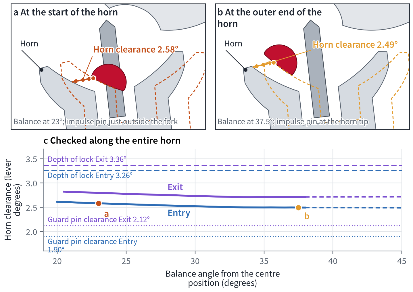
Horn clearance at the start of the horn (impulse pin just out of the fork), at the outer end of the horn and along the whole horn. In the model it is slightly larger on the inside than on the outside.
Guard pin clearance
Phase 5 · locking and supplementary arc · View the phase · View the manipulation
What is checked is the distance through which the lever can be turned away from the banking pin until the guard pin touches the safety roller. During the supplementary arc, the guard pin ensures that the tooth stays on the locking face in the event of a shock.
Position and manipulation: Turn the balance by more than 90° so that the full edge of the safety roller faces the guard pin. Then move the lever arm away from the banking pin until the guard pin rests against the safety roller. Repeat this at three points on the safety roller (90°, 180°, 270°) and from both banking pins (Pforzheim course notes). The critical position is “balance above the pallet fork” (Jendritzki).
Target value: Guard pin clearance must be present all the way round, equal on both sides and smaller than the depth of lock. When you press the guard pin against the safety roller, the tooth still rests securely on the lock (Bulova course). I set the guard pin so that the escapement always works: it must never rub, but it must be long enough that the tooth cannot leave the locking face when you move the lever back and forth. I keep the guard pin clearance nice and small, but distinct, because the guard pin is still at work at the beginning of unlocking too. What counts is the tested function, not the textbook value.
Point of contention: Helwig and the Theorie der Uhrmacherei require about half the lock to remain with the guard pin in contact. The Pforzheim question set puts guard pin clearance at about 1° beyond the drop lock, so measured from the banking pin, run to the banking plus 1°. On the model, that would be 2.78°/2.68°, with 0.48° and 0.68° of residual lock respectively. The tooth would stay on the lock, and guard pin clearance would remain larger than the run to the banking, as follows from Bossart's rules. Half the lock, by contrast, would leave only 1.63° of guard pin clearance on the entry side, less than the run to the banking of 1.78°.
After the pallets and banking pins had been adjusted, the newly designed 3D model initially had only 0.25° and 0.13° of lock respectively with the guard pin in contact. Had the guard pin simply been moved forward, it would have rubbed in the passing hollow of the safety roller. So the passing hollow was cut out deeper and the guard pin moved forward by 0.040 mm. On real safety rollers, the passing hollow is cut out more generously anyway. Guard pin clearance is now 1.90°/2.12° and residual lock 1.36° and 1.24° respectively, around 0.4 of the depth of lock. The complete procedure is shown in The exercise solved: which pallet, which direction, how much. So whenever you lengthen a guard pin, you must always check the passing hollow as well, because the guard pin must never touch its bottom (Bossart).
Key point: When the guard pin rests against the safety roller, the tooth stands securely on the lock. Guard pin clearance is adjusted last, see Adjusting the guard pin and horns.
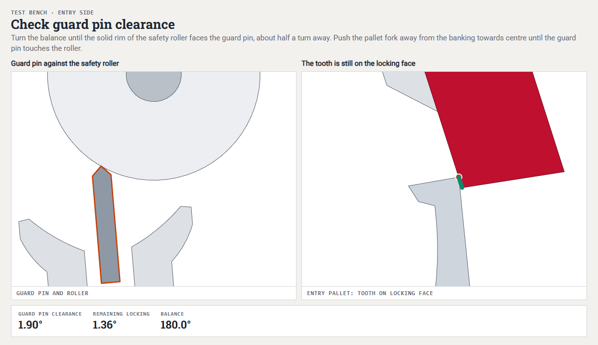 Open animation in a separate window
Checking guard pin clearance: on the left, the guard pin rests against the safety roller; on the right, the tooth is still on the lock. The damage a guard pin that is too short can do is shown in the fault atlas under Wedging and Overbanking.
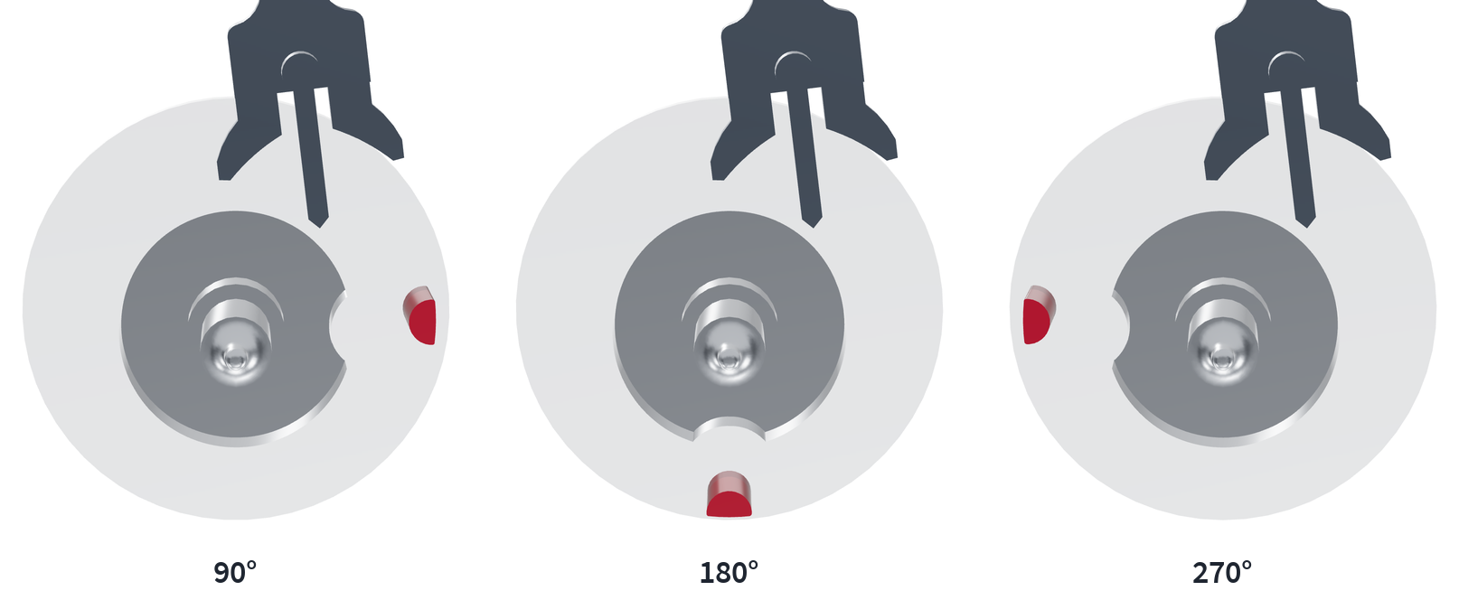
The three check positions of the safety roller: 90°, 180° and 270°, each with the guard pin facing the full edge (viewed from below).
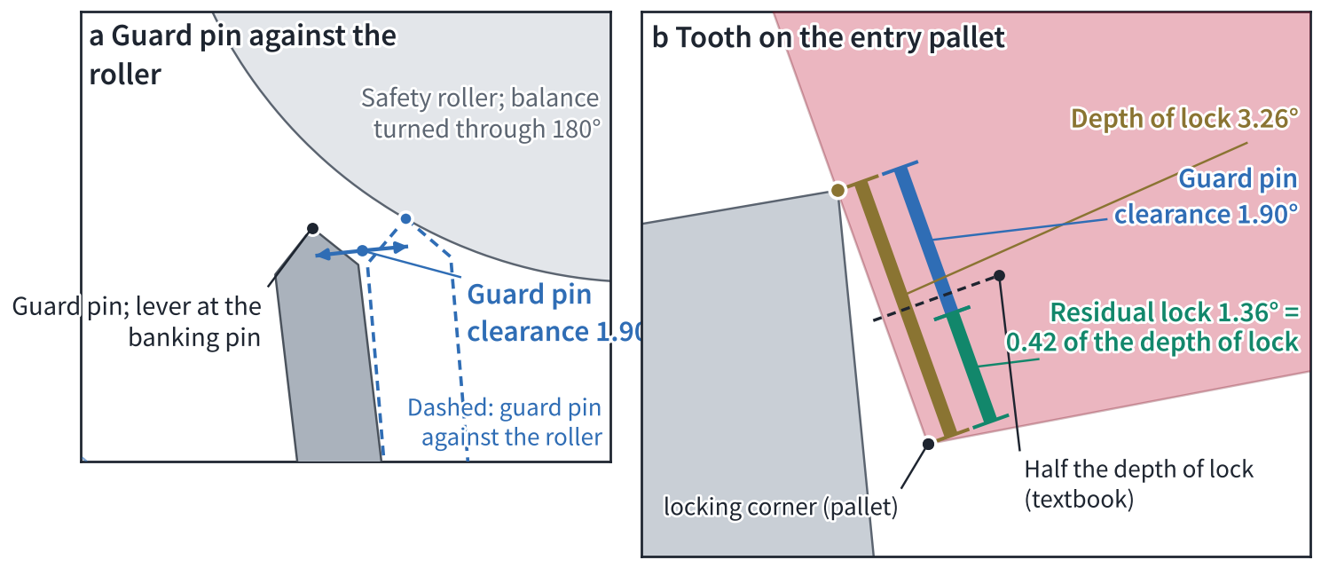
Guard pin clearance dimensioned, and the residual lock at the tooth: around 0.4 of the depth of lock in the model, about half the lock according to the textbook.
Beat error without a timing machine, and function tests
A movement is in beat when, at the dead point, the impulse pin lies on the line between balance and lever and the lever arm stands centrally between the banking pins (Bossart). Without a timing machine, you check this with the balance without its hairspring. Turn the balance until a tooth leaves the entry pallet, and make mark A on the rim opposite the centre of the stud. Then turn in the opposite direction until the tooth drops off the exit pallet, and make mark B. Now fit the hairspring so that the stud stands at the midpoint C between the two marks. Before any work on the balance, mark its position at the dead point.
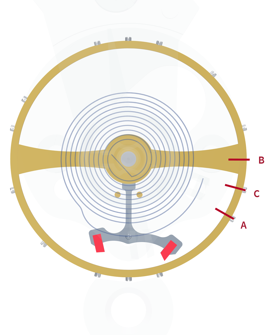
Beat marks on the rim: A and B where the tooth drops off the entry and exit pallets respectively, C in the middle for the stud.
Beat error is corrected on old watches made before 1950 by turning the hairspring collet, or on all modern watches by means of the rotatable stud carrier. According to an old rule, with the mainspring lightly wound, the balance must unlock to both sides (Jendritzki). Guide it with pegwood or a finger cot until the tooth just drops, and let it go. It must then also unlock on the opposite side by itself. If it did, the beat was considered adequate. Modern timing machines now display beat error in milliseconds, so we can go by the manufacturers' tolerances. On modern watches, a rule of thumb is to aim for less than 0.6 ms; with a fixed stud, on the other hand, under 1.2 ms is already very good and up to 6 ms tolerable.
But take care: in the vertical positions, beat error always changes somewhat because of bearing play. Weger expressly refuses to mask it by means of the banking pins or by retouching the hairspring.
Point of contention: According to the rule, beat error should be as small as the manufacturer requires (limits under What the timing machine measures and which values apply). Heffels, by contrast, reports on observatory chronometers on which the régleur deliberately left a small residual beat error, because doing so eliminated a bigger problem. An examination question from the Chamber of Crafts takes this up and asks about a beat error that is deliberately kept smaller in one position.
Finally come the function tests. The first is done before the pallet fork is fitted, the others on the adjusted movement:
Free running of the going train: Without the pallet fork and with the mainspring lightly wound, the going train runs down, and at the end the escape wheel must briefly swing back. This tells you that the going train runs freely (Bulova course; ETA likewise, before the pallet fork is fitted).
Stopping on the locking face: When fully wound, it must not be possible to stop pocket watches, or wristwatches over 24 mm, with the tooth on the locking face. After 24 hours of running, it must not be possible with any watch (Theorie der Uhrmacherei). The causes are given under Stopping on the locking face or the impulse face.
Self-starting: Wind the mainspring by only 2–3 ratchet-wheel teeth, bring the balance into the “stopping on the impulse face” position, hold it there and continue winding in the horizontal position. Small watches start by themselves after 4–5 ratchet-wheel teeth, medium-sized ones after half a turn of the mainspring, large ones after one to two turns (Theorie der Uhrmacherei).
Guard pin against the safety roller (old pocket watches only): Press the guard pin against the safety roller, or push the going train backwards, while turning the balance back and forth. Nothing must catch. If the impulse pin catches on the horn tip, guard pin clearance is too large (Bossart, Bulova course). This test reproduces what happens when the hands are set backwards.
Rebanking: In the horizontal position and fully wound, the impulse pin must not strike the outside of the horns (Knocking, rebanking, overbanking). Where the limit lies is given under The ladder of safety clearances and the rebanking limit.
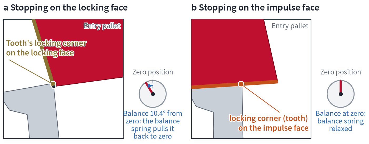
Stopping on the locking face (left) and on the impulse face (right): when fully wound, the first position must not hold; from the second, the watch must start by itself.
Check | Position | Target value | Our model (entry/exit, at the lever) |
|---|---|---|---|
dead point, mainspring run down | perceptible, no free travel; 0.01–0.03 mm | 0.48° (≈ 0.026 mm) | |
impulse pin at fork corner and horn, full horn length | greater than horn clearance: no tooth on impulse in any position, plus a small safety margin | far fork corner 0.045/0.041 mm (2.27°/2.04°); the horn catches, residual lock at least 0.65°/0.54° | |
little force, guide the balance with the thumb | all teeth free, both pallets | free everywhere | |
instant of drop | ⅛ of the impulse face, no tooth on the impulse face | 1.48°/1.68° | |
instant of drop, tooth's let-off corner in front of the pallet's let-off corner | inside about equal to outside, around 1½° at the escape wheel | inside 2.03°, outside 1.80° at the escape wheel | |
instant of drop | equal on both sides | 0.90°/1.20°, unequal (0.30° difference) | |
lever against the banking pin | ¼ of the impulse face, equal on both sides | 3.26°/3.36° | |
from the drop to the banking pin | equal on both sides | 1.78°/1.68° | |
lift the lever away, or guard pin against the safety roller | immediately back to the banking pin | – | |
impulse pin just out of the fork plus 7–10° (model ≈ 28°), then along the whole horn | at least the run to the banking, smaller than depth of lock | 2.58°/2.79° at balance 23° (2.54°/2.75° at 28°); along the horn 2.49–2.61°/2.71–2.82° | |
balance turned more than 90°, three points on the safety roller | tooth stays securely on the lock | 1.90°/2.12° | |
dead point | impulse pin on the balance–lever line | – |
Moving the pallet stones and adjusting the banking
This is the heart of workshop work on the escapement. At the end of this chapter, the exercise can be solved. Before adjustment, our model had 1.22° of run to the banking on the entry side, but only 0.34° on the exit side. Which pallet do we change, in which direction, and by how much?
A typical exam question belongs here too: the drop lock is too small. How do you change it, and what happens at the opposite pallet as a result? We first observe and explain, then try it out ourselves, go through workshop practice with its borderline cases, and finally solve the exercise. All angles are given in lever degrees unless otherwise stated. The exact figures for aspiring master watchmakers are given under Moving the pallet stones in numbers.
Out means deeper
The pallet stones sit in slots in the pallet arms and are traditionally fixed with shellac, a natural resin that softens when warm. This is why they are only ever moved with heat applied. The pallets of modern watches can also be moved with heat, even though industry nowadays uses special adhesives rather than natural shellac. If you push a pallet further out of its slot, it projects further into the escape wheel and the lock becomes deeper. If you push it in, the lock becomes shallower.
The Pforzheim handout shows this in a sketch. Pressure on the rear end of the pallet deepens the lock, pressure on the impulse-face side makes it shallower, and you can see whether the pallet has moved from the gap at the back of the slot. The Würzburg master-course notes say “nach außen” and “nach innen” (outwards and inwards), Bossart says “herausziehen” and “hineinschieben” (pull out and push in). The expression “zu tief eingeschoben” (pushed in too deep) is best avoided, because it can mean either. On the pallet adjustment model further down, a plus on the pallet slider means that the pallet is pushed out.
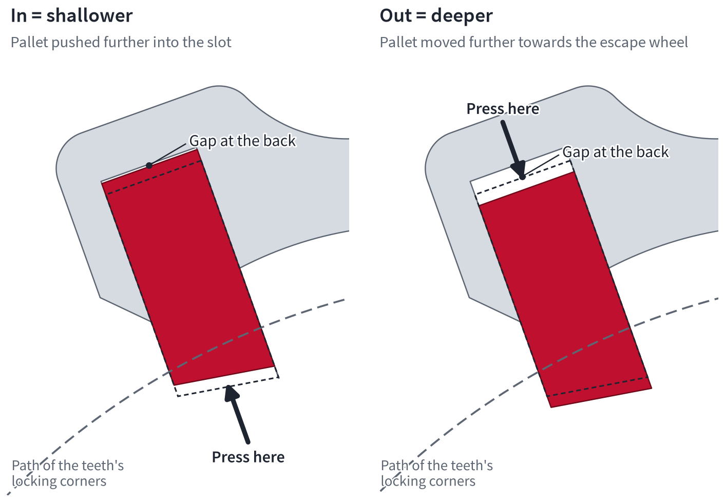
Out means deeper: pressure from behind pushes the pallet towards the escape wheel and deepens the lock; pressure from the front makes the lock shallower. The gap at the back of the slot shows whether the pallet has moved (displacement exaggerated).
A puzzling observation and two questions
Let us begin with an experiment on the model before adjustment. We pull only the exit pallet out by 0.01 mm and leave everything else as it is. That depth of lock and drop lock on the exit side each increase by 0.32° was to be expected. But the drop lock on the entry side also increases, by 0.26°, even though nobody touched anything there. And the run to the banking on the entry side decreases by exactly the same amount. Why?
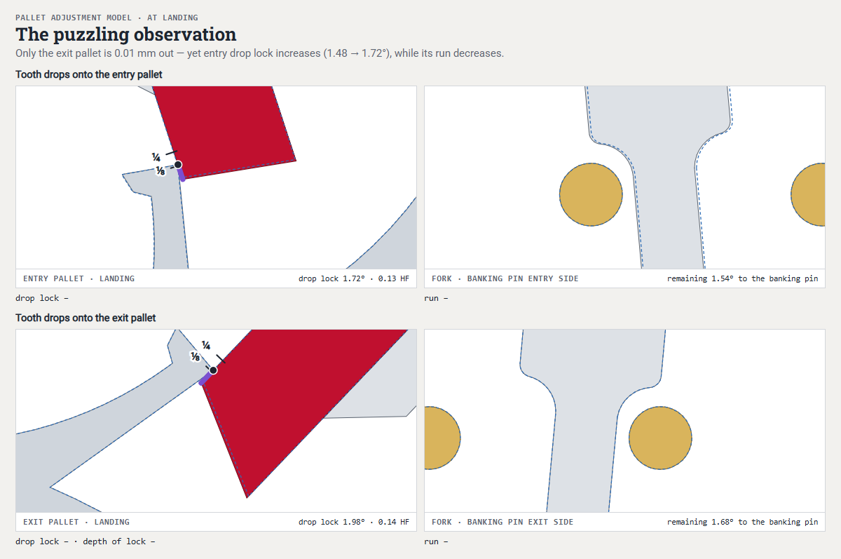 Open animation in a separate window
The puzzling observation on the adjusted model: only the exit pallet is pushed out by 0.01 mm, and yet the tooth also lands deeper on the entry pallet (drop lock 1.48° → 1.72°, run to the banking 1.78° → 1.54°).
The answer lies in two questions you can ask yourself with every adjustment.
Where does the tooth land? At the instant of drop, one tooth leaves one pallet and another tooth drops onto the other. At this instant, the lever is exactly where impulse ends at the first pallet. If the exit pallet stands further out, the let-off corner of the pallet reaches deeper into the escape wheel. The tooth therefore leaves it later, the lever has turned further by then, and the entry pallet is deeper in the escape wheel when another tooth drops onto it. The drop lock therefore depends on both pallets: on its own pallet and on the opposite pallet, which released a tooth shortly before.
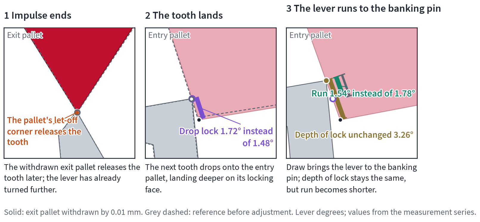
Where impulse ends on one pallet determines how deep the tooth lands on the other. After that, draw pulls the lever to the banking pin.
Where does the lever come to rest here? Draw pulls it as far as the banking pin. The depth of lock with which the tooth then rests on the locking face is therefore determined only by this banking pin and the pallet on the same side. The pallet on the opposite side has no influence on it.
The run to the banking is the difference between the two, i.e. depth of lock minus drop lock. If the depth of lock on the entry side stays the same while the drop lock there increases, the run to the banking must shrink. That explains the observation.
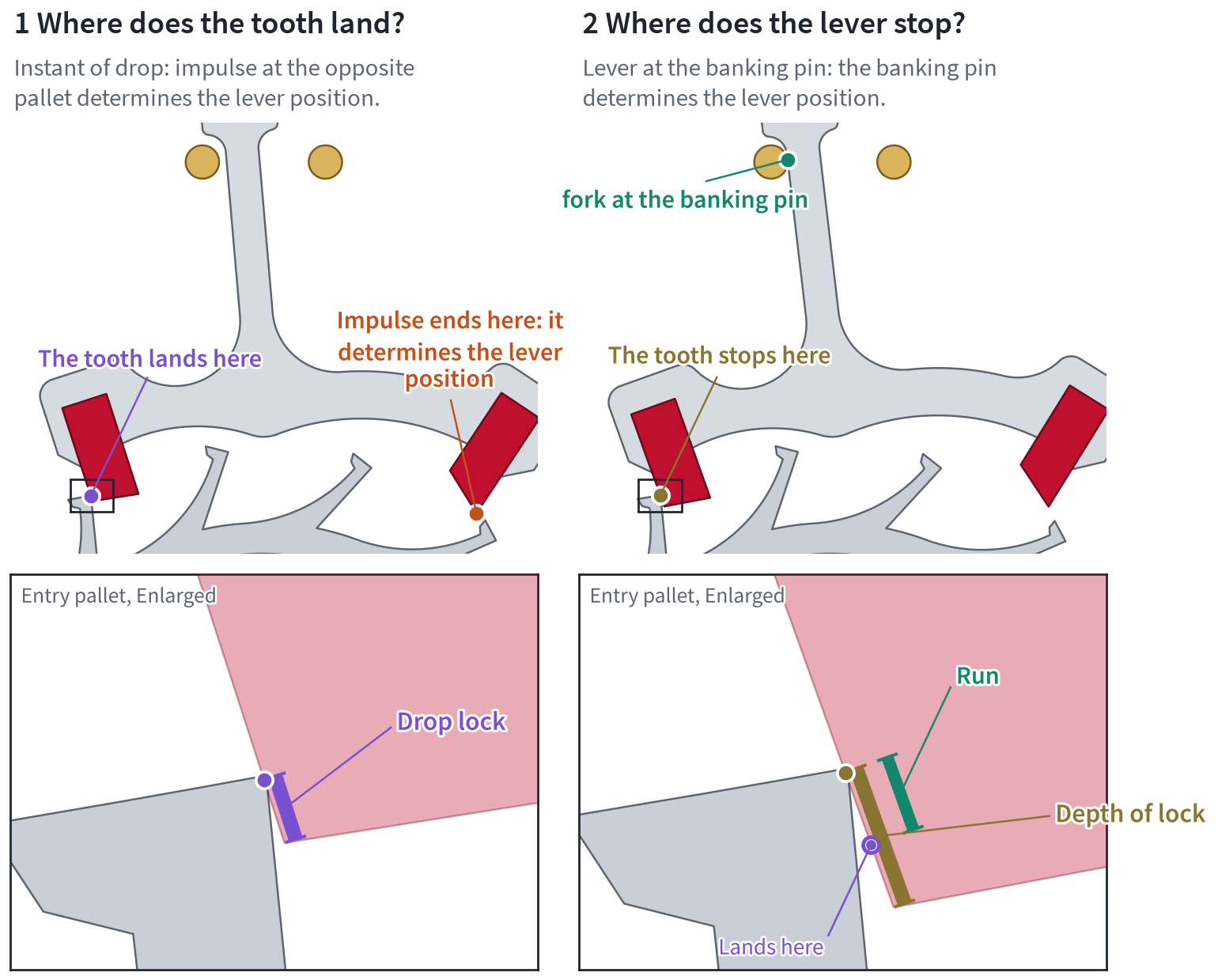
Two questions for every adjustment: Where does the tooth land (drop lock)? Where does the lever come to rest (depth of lock)? The difference between depth of lock and drop lock is the run to the banking.
This gives us the core rule. If you push a pallet out, the drop lock increases on both sides, the depth of lock only on its own side, and the run to the banking decreases only on the opposite side. If you push it in, everything works the other way round. A banking pin, by contrast, does not change the drop lock, because the tooth has long since landed by the time the lever arm reaches the banking pin. It changes depth of lock, run to the banking, horn clearance and guard pin clearance on its side, all by the same amount. Guard pin clearance stays the same when the pallets are moved, because it is measured from the banking pin.
Quantity | Exit pallet 0.01 mm out | Entry pallet 0.01 mm in |
|---|---|---|
Drop lock, entry | +0.26° | −0.30° |
Drop lock, exit | +0.32° | −0.36° |
Depth of lock, entry | unchanged | −0.30° |
Depth of lock, exit | +0.32° | unchanged |
Run to the banking, entry | −0.26° | unchanged |
Run to the banking, exit | unchanged | +0.36° |
Guard pin clearance, both sides | unchanged | unchanged |
On the substance, the sources almost agree. Bossart writes that when a pallet is pulled out, the lock on the other pallet becomes greater too. Wilkinson and the Bulova School course booklets include the same in their rules, and in Jendritzki the run to the banking depends on the position of the pallet on the other side. Only one passage in the Würzburg master-course notes assigns the smaller run to the banking to the side that was moved. The model, the Pforzheim table and the other sources, by contrast, show clearly that it becomes smaller on the opposite side.
As a rule of thumb for our model, remember that 0.01 mm at the pallet amounts to around ⅓° at the lever. At the balance, because of the lever ratio of about 3, it is around 1°.
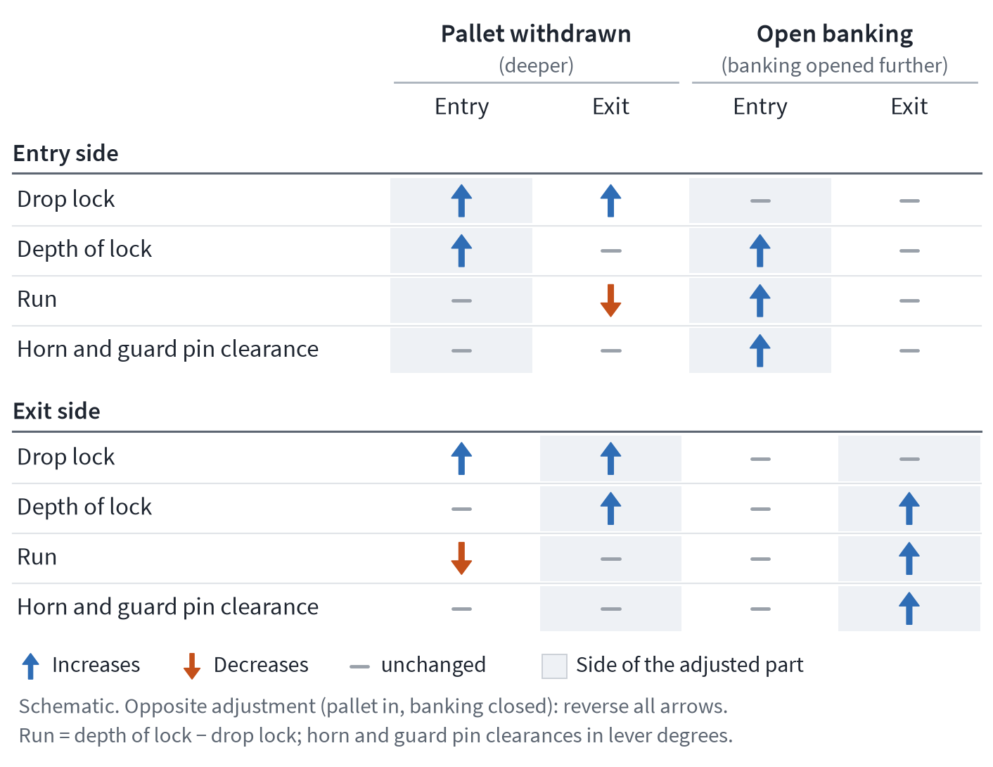
What affects what: each pallet affects both drop locks, its own depth of lock and the run to the banking on the opposite side. Each banking pin affects only its own side, where it acts on depth of lock, run to the banking, horn clearance and guard pin clearance, but not on the drop lock.
Key point: The pallet changes the drop lock on both sides and the depth of lock on its own side. The banking pin changes only the depth of lock, run to the banking, horn clearance and guard pin clearance on its side. The run to the banking is always the difference between depth of lock and drop lock.
Try it yourself: the pallet adjustment model
It is best to try out the core rule for yourself. The pallet adjustment model shows both pallets and the lever arm at the banking pin, with the values for both sides below. Each pallet can be moved in steps of 0.005 mm, and each banking pin can be adjusted by up to 0.5°. A ghost image also shows the setting according to the workshop rule. If the escapement no longer runs, the program reports the fault pattern, such as “blocked” or “tooth drops onto the impulse face”.
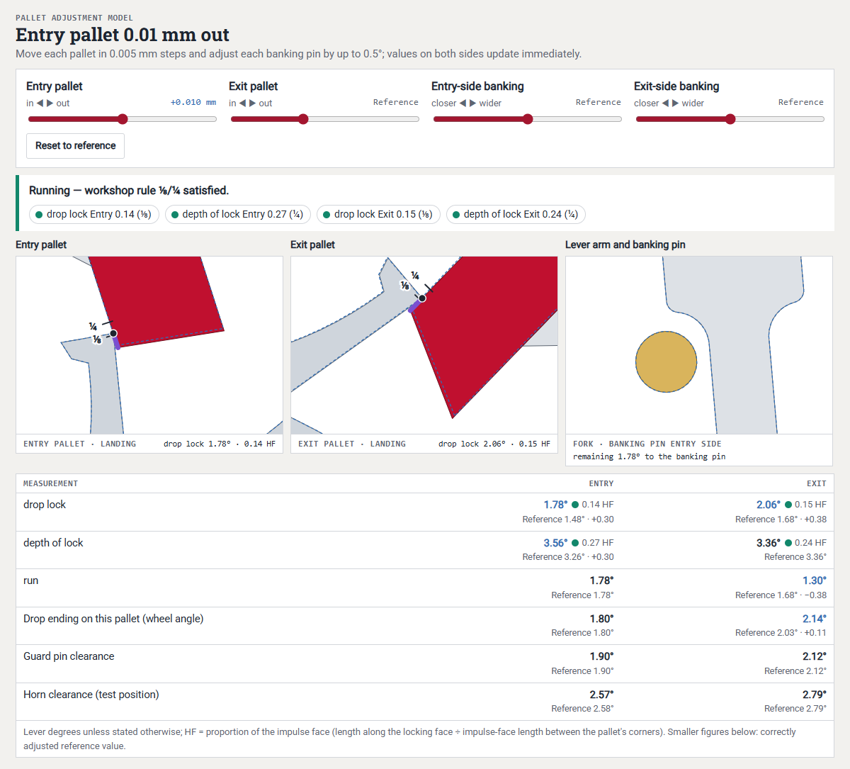 Open animation in a separate window
The pallet adjustment model: when you move the pallets or adjust the banking pins, the values for both sides change immediately.
For the five tasks, it is worth first predicting the result, then trying it out and finally explaining it.
1. The exit pallet is pulled out by 0.01 mm. What changes, and where?
The drop lock increases on both sides, the depth of lock only on exit, and the run to the banking decreases on entry, each by around 0.3°. Guard pin clearance and the run to the banking on exit stay the same.
2. The banking pin on entry is opened by 0.25°. What stays the same?
Both drop locks and all values on exit stay the same. On entry, the depth of lock, run to the banking, horn clearance and guard pin clearance each increase by about 0.25°.
3. Both pallets move in. At what point does the tooth drop onto the impulse face?
Starting from the workshop rule, the tooth drops onto the impulse face from just under 0.025 mm, and it does so first on exit. At 0.024 mm it still just lands on the locking face there. The drop lock decreases about twice as fast as when a single pallet is moved, because each pallet acts on both sides (Borderline cases).
4. On entry, the run to the banking is too large and the drop lock is tight. Which pallet do we pull out?
You pull out the exit pallet, because it increases the drop lock on entry and reduces the run to the banking there. If you pull out the entry pallet instead, the run to the banking on entry remains unchanged.
5. In the exercise (“Load exercise” button), which pallet must be moved, in which direction and how far?
It is best to solve the exercise yourself first and then switch between the four pre-calculated states: before adjustment, Route 1, Pin and Route 2. The sliders are locked while you do so. The solution is at the End of this chapter.
Adjusting the banking
This section applies only to movements with adjustable banking, above all pocket watches and older movements. Today, fixed stops are the rule: the Geneva Seal requires two fixed stops and expressly excludes banking pins, almost all manufacturers today bank the pallet fork against the pallet bridge, and data sheets from ébauche manufacturers sometimes state it in full: “échappement avec butées fixes”. With fixed banking, normally only moving the pallets and replacing components remain, which is why the exercise shows both routes. If there is absolutely no alternative and no replacement part is available, the banking can be corrected very carefully by punching (staking) or filing to save the watch, provided you master this work with the utmost precision.
If you adjust a banking pin inwards, that is, towards the centreline, the depth of lock, run to the banking, horn clearance and guard pin clearance on that side become smaller. The impulse pin then engages more deeply in the fork slot, and unlocking becomes easier. If you adjust it outwards, everything works the other way round, and the drop lock stays the same in both cases. On the model, the banking pins were opened by 0.45° on entry and by 1.20° on exit. As long as the guard pin had not yet been readjusted, the guard pin clearance increased by almost exactly the same amount, from 2.57°/2.07° to 3.01°/3.23°. Whether draw becomes stronger when the banking is opened, as the Pforzheim handout and the Würzburg course notes teach, is clarified in Draw in more detail.
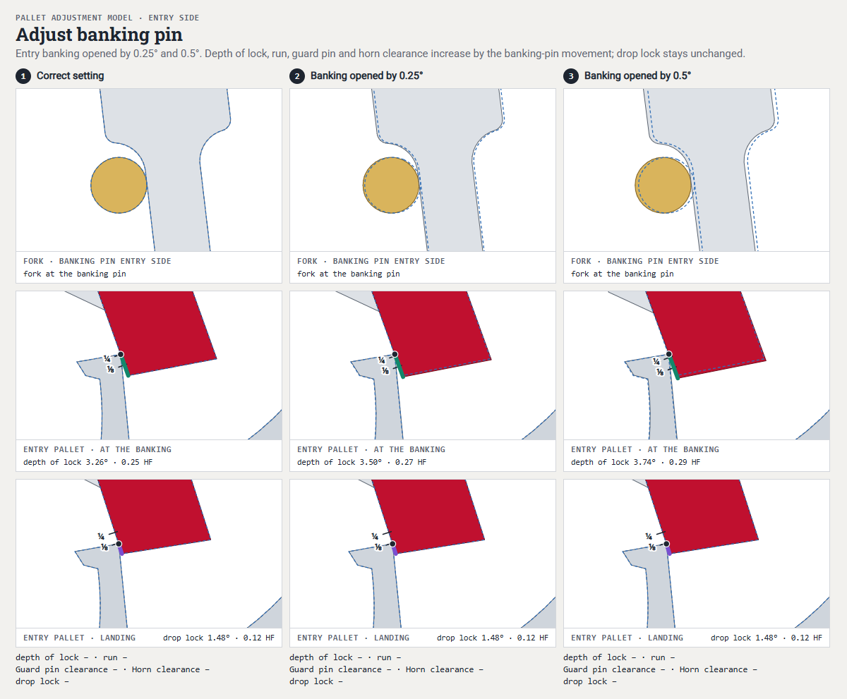 Open animation in a separate window
Banking pin adjusted outwards: depth of lock, run to the banking, guard pin clearance and horn clearance increase with it, and the drop lock stays the same.
The banking pin should be vertical. An inclined banking pin stops the pallet fork at a different point depending on the endshake, and the watch runs differently in the dial-up and dial-down positions. Smith therefore adjusts it twice at right angles so that the contact face stays vertical. Eccentric pins, which are turned rather than adjusted, avoid this. Banking pins never receive oil, because even a sticky film holds the pallet fork fast. It is even advisable to get into the habit of cleaning the lever banking with pegwood every time the movement is cleaned, because unusual contamination can occur at this point; it can have a sticking effect and becomes visible as tiny black dots at 40× magnification.
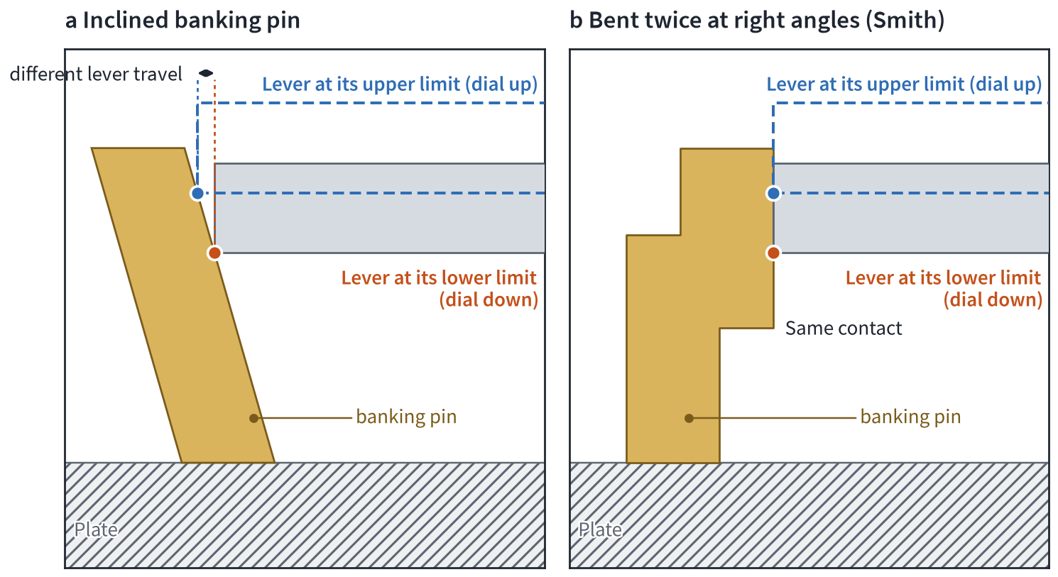
An inclined banking pin stops the pallet fork at a different point depending on the pallet fork's height. The result is a rate difference between dial up and dial down.
Good to know: the Boley catalogue lists an adjusting tool with which banking pins can be adjusted without removing the balance cock and balance.
It is disputed whether guard pin clearance may be corrected via the banking pins. According to the Pforzheim handout, never. The Würzburg master-course notes name the banking pins as the second option, and Bossart sets the play between impulse pin and horns via the banking pins. As early as 1903, Schultz describes where this can lead: the banking is set narrower, the guard pin binds on the safety roller, it is shortened, and the watch later stops intermittently. The core rule yields a clear distinction: the banking is the right place for the correction only when horn clearance, run to the banking and guard pin clearance on one side are all wrong together.
A historical method is banking to the drop. For movements with eccentric pins, the Bulova School course booklets derive the banking directly from the pallets. The method produces different proportions from our workshop rule and has four steps:
Remove the balance and turn one banking pin close to the centreline. Draw holds the pallet fork against the banking pin.
Then turn the banking pin back until the tooth just drops off the opposite pallet. The depth of lock now equals the drop lock, according to Bulova about ¼ of the width of the impulse face.
Set the other banking pin in the same way. Over one revolution of the escape wheel, the fork then moves the same distance away from the centreline on both sides. With the balance fitted, guard pin clearance is barely perceptible, at most ½°, or up to 1° with deeper lock.
Finally, open both banking pins until the depth of lock has increased by about ⅓. This increase is the run to the banking.
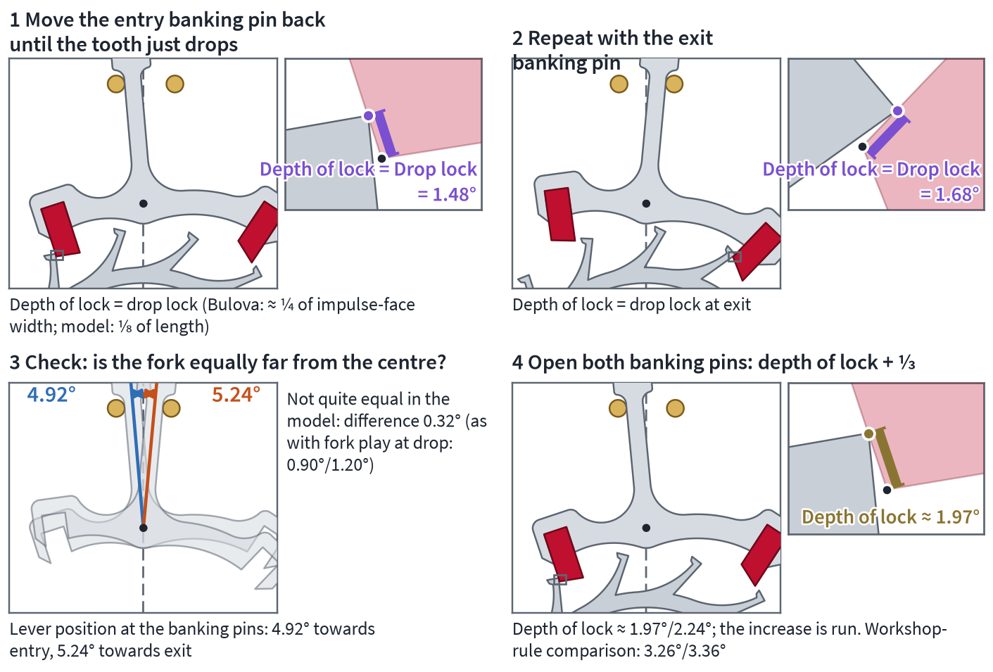
Banking to the drop, a historical method after Bulova: first each banking pin is turned back until the tooth drops, then both are opened until the depth of lock has increased by about a third.
Key point: if horn clearance, run to the banking and guard pin clearance on one side are all wrong together, the cause is the banking pin. If only guard pin clearance is wrong, the cause is the guard pin.
One pallet or both? The decision path
Three golden rules from the Pforzheim training apply to the decision. First, all teeth drop safely onto the lock. Second, the depth of lock is equal on both sides. Third, it is no greater than necessary. Our measure is a quarter of the length of the impulse face (Workshop rule).
If you move both pallets by the same amount, the fork position and the beat stay as they are. If you move only one, the centre position of the pallet fork shifts, and the beat must then be set again. Adjusting the fork is not a solution with high-quality pallet forks of hardened steel, because they break and cannot be bent. According to Bossart, draw and the distribution of drop decide which pallet to move. If draw on the entry pallet is large, you would tend to pull out the exit pallet. If the inside drop is smaller than the outside drop, you would tend to pull out the entry pallet. How to choose the pallet according to fork play at the instant of drop is explained under Fork play at the instant of drop and the pallet-stone rule. The basic setting is this: when the pallet fork is in the centre, the locking corners of the teeth lie roughly at the middle of the pallets' impulse faces.
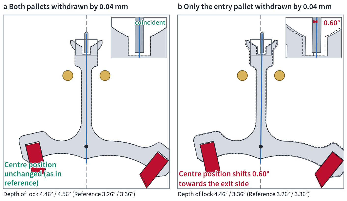
If both pallets are moved by the same amount, the fork position and beat stay the same. If only one pallet is moved, the centre position of the pallet fork shifts, and the beat must be set again.
One case remains open in which textbook and model do not quite agree: unequal drop lock with equal run to the banking. According to the Würzburg master-course notes, this cannot be compensated by moving the pallets, because the impulse-face angle is wrong, and a new pallet is needed. Bossart, too, advises that with unequal lock the pallet should be replaced or reground by a jewel grinder. The model before adjustment, however, shows that a pallet does not change the two drop locks by quite the same amount. Per 0.01 mm, the exit pallet changes the drop lock on its own side by 0.30 to 0.32° and on the opposite side by 0.26°, and the entry pallet changes it by 0.30° on its own side and by 0.36° on the opposite side. If you therefore push the exit pallet in by 0.01 mm and the entry pallet by about 0.007 mm, both runs to the banking increase by around 0.25°, and the drop lock decreases by just under 0.1° more on exit than on entry. On the adjusted model, the effects add up almost exactly: the drop lock decreases by 0.46° on entry and by 0.56° on exit (from 1.48°/1.68° to 1.02°/1.12°), the run to the banking increases by 0.26° on both sides, and the difference between the drop locks falls from 0.20° to 0.10°. The gain is therefore small, because for 0.1° of equalisation you shift both drop locks by around half a degree. A clear difference is therefore still corrected as in the textbook, with a new or reground pallet.
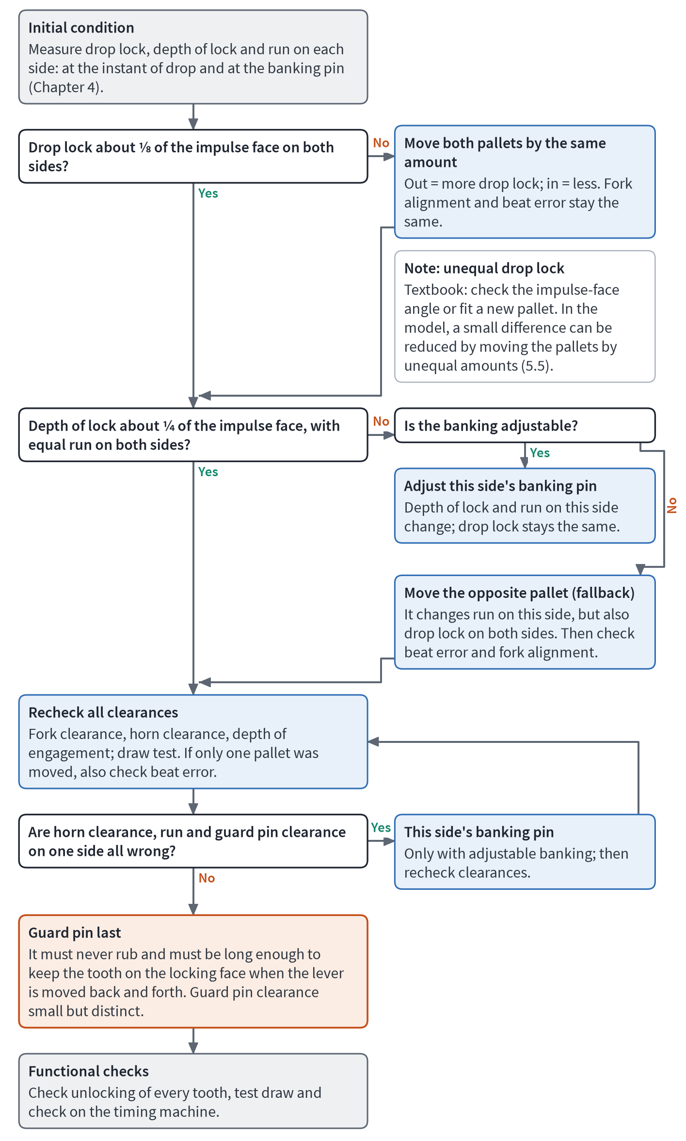
The decision path: first set the drop lock with the pallets, then depth of lock and run to the banking with the banking pins or, with fixed banking, again with the pallets. Guard pin clearance always comes last.
Adjustment | Drop lock | Depth of lock | Run to the banking | Guard pin clearance | Horn clearance | Fork clearance | Drop | Unlocking |
|---|---|---|---|---|---|---|---|---|
one pallet out | + both sides | + own side | − opposite side | unchanged | unchanged | unchanged | slightly | own side harder |
both pallets out | + both, about double | + both | − both | unchanged | unchanged | unchanged | slightly | harder |
banking pin outwards | unchanged | + own side | + own side | + own side | + own side | unchanged | unchanged | own side harder |
lengthen guard pin | unchanged | unchanged | unchanged | − both | unchanged | unchanged | unchanged | unchanged |
larger impulse pin | unchanged | unchanged | unchanged | unchanged | − both | − | unchanged | unchanged |
regrind horns | unchanged | unchanged | unchanged | unchanged | + | may increase | unchanged | unchanged |
Borderline cases: when the tooth drops onto the impulse face
How far can you move the pallets before the escapement fails? Before adjustment, with 1.22° and 0.34° of run to the banking, our model ran only if both pallets were pushed in together by at most just under 0.03 mm or pulled out by at most just under 0.01 mm. The margin was therefore just under 0.04 mm. With the workshop-rule setting, it ranges from just under 0.025 mm in to 0.045 mm out, just under 0.07 mm in total.
The inward limit depends on the drop lock, and the banking pins do not change that. After adjustment, this limit even moves a little closer, because the pallets already sit 0.005 mm further in. The outward limit depends on the run to the banking, and on exit this has grown from 0.34° to 1.68°. This shows that the run to the banking is a reserve.
(a) Pallets too far in. The drop lock approaches zero on both sides. Beyond the limit, the tooth no longer drops onto the locking face but directly onto the impulse face of the other pallet. The escape wheel then tries to push the pallet fork back without the balance having unlocked it. The horns and safety roller decide whether the pallet fork flips over, and in our model they prevent it. On landing, the impulse pin is still in the fork slot, the tooth presses the fork corner against it, and on its way outwards the balance has to push the pallet fork back along the inside of the horn. 0.005 mm beyond the limit, it turns the escape wheel back by 0.6 to 0.9° in the process and loses oscillating energy. At a balance angle of about 33°, the impulse pin reaches the horn tip and briefly holds the pallet fork there. From about 38°, the safety roller pushes the guard pin, and with it the pallet fork, back far enough for the tooth to return over the pallet's locking corner onto the locking face, and at around 40° the pallet fork rests against the banking pin again. The half-oscillation therefore ends braked, but without the pallet fork flipping over. If the pallets are so far in that the depth of lock becomes smaller than the guard pin clearance, in the model from about 0.04 mm, even this safety feature no longer helps. The tooth then stays on the impulse face, the guard pin rubs against the safety roller throughout the supplementary arc, and on the return swing the escape wheel already presses the fork against the impulse pin before the impulse pin unlocks. According to the description by timing-machine manufacturer Witschi, the beat on the scope then shows only two packets instead of three. The remedy is to move the pallets out. The same pattern arises with pallets that are too short, too great a distance between escape wheel and pallet fork, too much endshake and sideshake, or an escape wheel that is out of round (older watches). Moving the pallets then helps only to a limited extent, and the bearings, escape wheel or pallet fork must be repaired or replaced.
The model calculates without inertia. In practice, however, the pallet fork certainly can flip over. It can usually be seen nicely in pocket watches with a heavy balance that is then swinging with only a few degrees of amplitude. In today's watches it can hardly be provoked, perhaps because of differences in the dynamic drop. In running, the tooth also bounces on landing (What really happens), and the Pforzheim handout warns that it can briefly jump onto the impulse face in the process.
But beware of the in-between case: statically, that is, guided slowly by hand, the tooth drops onto the impulse face, but in running it still just lands on the locking face, and the watch runs. An escapement must not be adjusted like this. I do not gamble on it working, because every tooth must drop safely onto the locking face even when guided slowly. Adjusting close to the limit throws the reserve away.
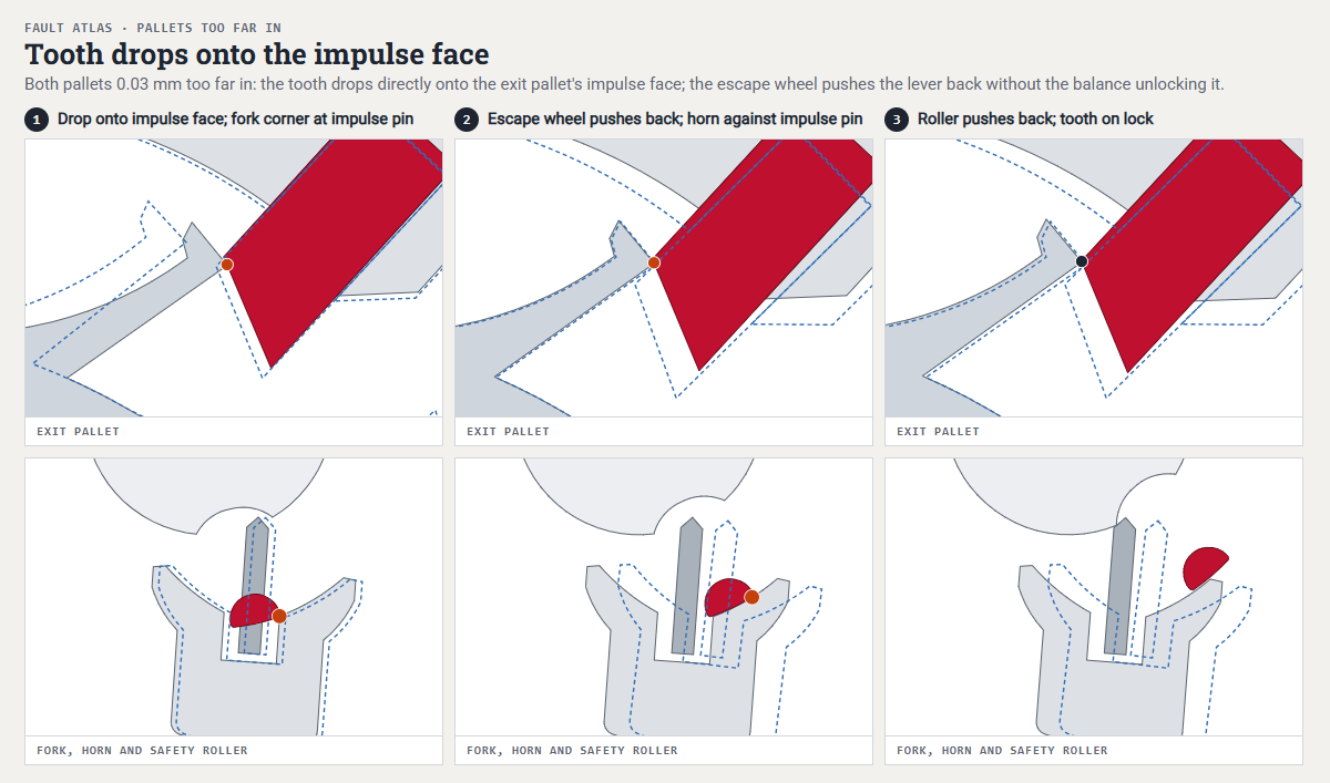 Open animation in a separate window
Pallets too far in: the tooth drops directly onto the impulse face, and the escape wheel pushes the pallet fork back without the balance having unlocked it. In the model, the fork corner, horn and safety roller catch the pallet fork, the balance is braked, and the pallet fork does not flip over. The Fault atlas shows the whole sequence.
(b) Pallets too far out. The lock becomes too deep. At every unlocking, the balance has to do more work against draw and therefore loses more energy. The amplitude falls and the watch loses, most of all in the vertical positions, where the amplitude is smaller anyway. In the worst case, the watch stops on the lock because the balance can no longer unlock the pallet fork. On the scope, the first two packets are then far apart, as in the scope image “lock too strong”. The Witschi image “unlocking too strong”, with strong first packets lying close together, on the other hand shows a different fault. At the same time, the run to the banking on the opposite side shrinks. That is why, before adjustment, the limit was already at just under 0.01 mm.
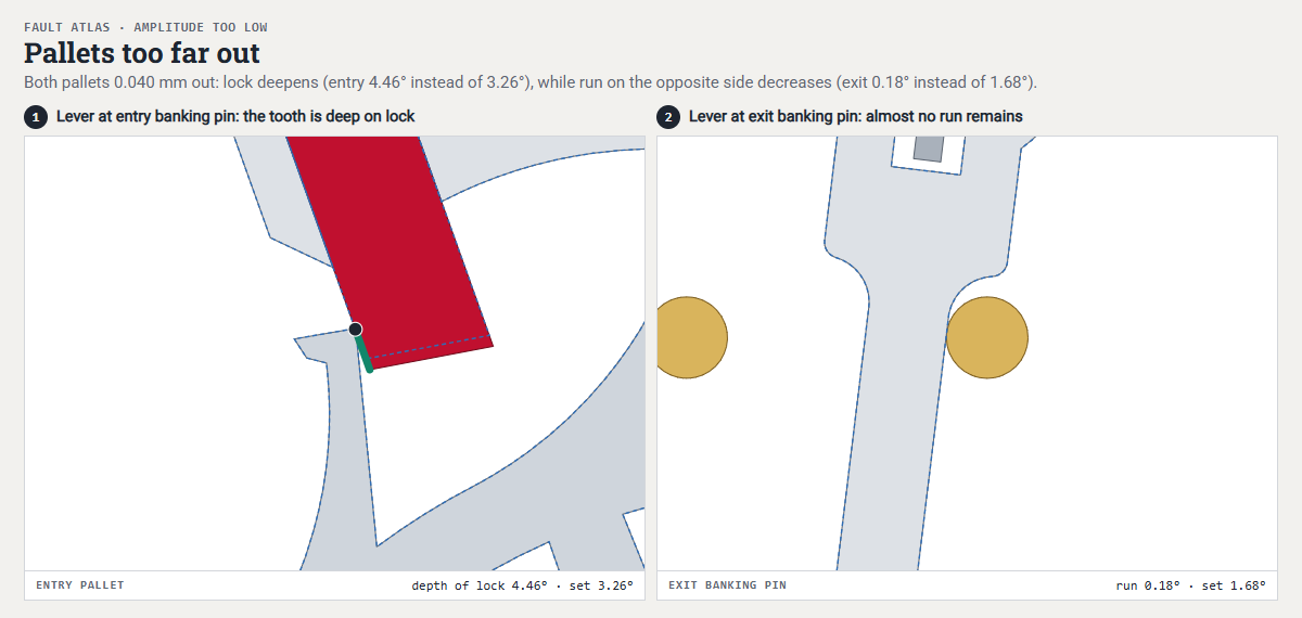 Open animation in a separate window
Pallets too far out: the lock is deep, unlocking is hard, and on the opposite side hardly any run to the banking remains.
(c) No run to the banking left. If the opposite pallet is too far out or the banking pin is set too narrow, the tooth is still on the impulse face when the lever arm reaches the banking pin. The tooth then cannot drop. On the return swing, the balance pushes the escape wheel back, in the model by around 10° per half-oscillation, and then the escape wheel drives forward again. It rocks back and forth and makes no progress. The escapement catches, in other words it locks up. Before adjustment, pulling the entry pallet out by 0.01 mm or setting the banking 0.5° narrower on both sides was already enough for this. With the workshop-rule setting, the run to the banking on exit lasts until the entry pallet has been pulled out by just over 0.045 mm. Only then does the escapement lock up. The exit pallet may even go out as far as 0.07 mm, because it uses up the run to the banking on entry more slowly. Via the banking, the escapement locks up only when the banking is set 1.74° narrower on both sides (the exit banking pin alone likewise 1.74°, the entry banking pin alone 1.84°), that is, almost exactly by the run to the banking of the respective side.
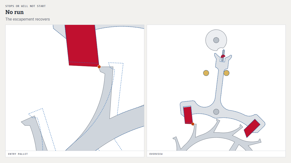 Open animation in a separate window
No run to the banking: the tooth does not get clear of the impulse face, the escape wheel rocks back and forth, and the escapement locks up. The Fault atlas shows the sequence.
(d) Banking pin too wide. The depth of lock and run to the banking on this side grow beyond the workshop rule. The lock becomes too deep, unlocking hard, and the balance loses more energy at every unlocking. Horn clearance and guard pin clearance grow to the same extent, on the model by almost exactly the amount by which the banking pin was opened. The residual lock, that is, the lock that still remains with the guard pin or horn in contact, therefore does not change. What can become tight, however, is the depth of engagement of the impulse pin relative to the horn clearance, because according to the textbooks, the further out the banking pin is, the more readily the impulse pin strikes the fork corner on the return swing. On the model with the entry banking pin 1.0° too wide, during a shock in the supplementary arc it is first the guard pin at the safety roller that catches the pallet fork. When the guard pin is in the passing hollow, that is, as long as the balance is less than 38.5° from the centre position, the horn catches the impulse pin, first with its tip and from about 33° with the horn curve, at least 0.17 mm away from the fork corner. The impulse pin never strikes the fork corner itself. The residual lock at the guard pin is around 1.4° far out in the supplementary arc and still 0.77° shortly before the passing hollow. On the return swing at the horn it is at least 0.68°, even slightly more than with a correctly set banking pin (0.65°). Things become tighter on the ordinary return swing without a shock: the impulse pin engages the far fork corner only 0.028 mm deep instead of 0.045 mm, or 1.3° instead of 2.3° as lever angle, with a horn clearance of 3.56°. No tooth gets into impulse in the process. The function is retained; only the engagement becomes shallower (Depth of engagement).
According to the fault tables in Bossart and in Theorie der Uhrmacherei, on the other hand, banking that is too wide causes the horn clearance to be smaller than the run to the banking, and the horn rubs. Bossart explains this with the fast balance at the end of impulse: the impulse pin leaves the fork before the pallet fork has completed its run to the banking. Our model does not confirm that a banking pin that is too wide causes this on its own, not even with the entry banking pin 1.0° too wide. In the model, the banking pin changes horn clearance and run to the banking in a ratio of 1 : 1, and their difference depends on the horn, the impulse pin and the position on landing. However, the model calculates without inertia and therefore cannot test Bossart's explanation with the fast balance.
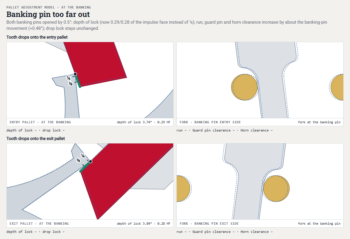 Open animation in a separate window
Banking pins too wide: both banking pins are set 0.5° wider. Depth of lock, run to the banking, guard pin clearance and horn clearance increase by around 0.48°, and the drop lock stays the same.
Worn impulse faces must be distinguished from this, because a wear track in the second and third thirds of the pallet is not a classic escapement fault (Not a fault: the delayed impulse).
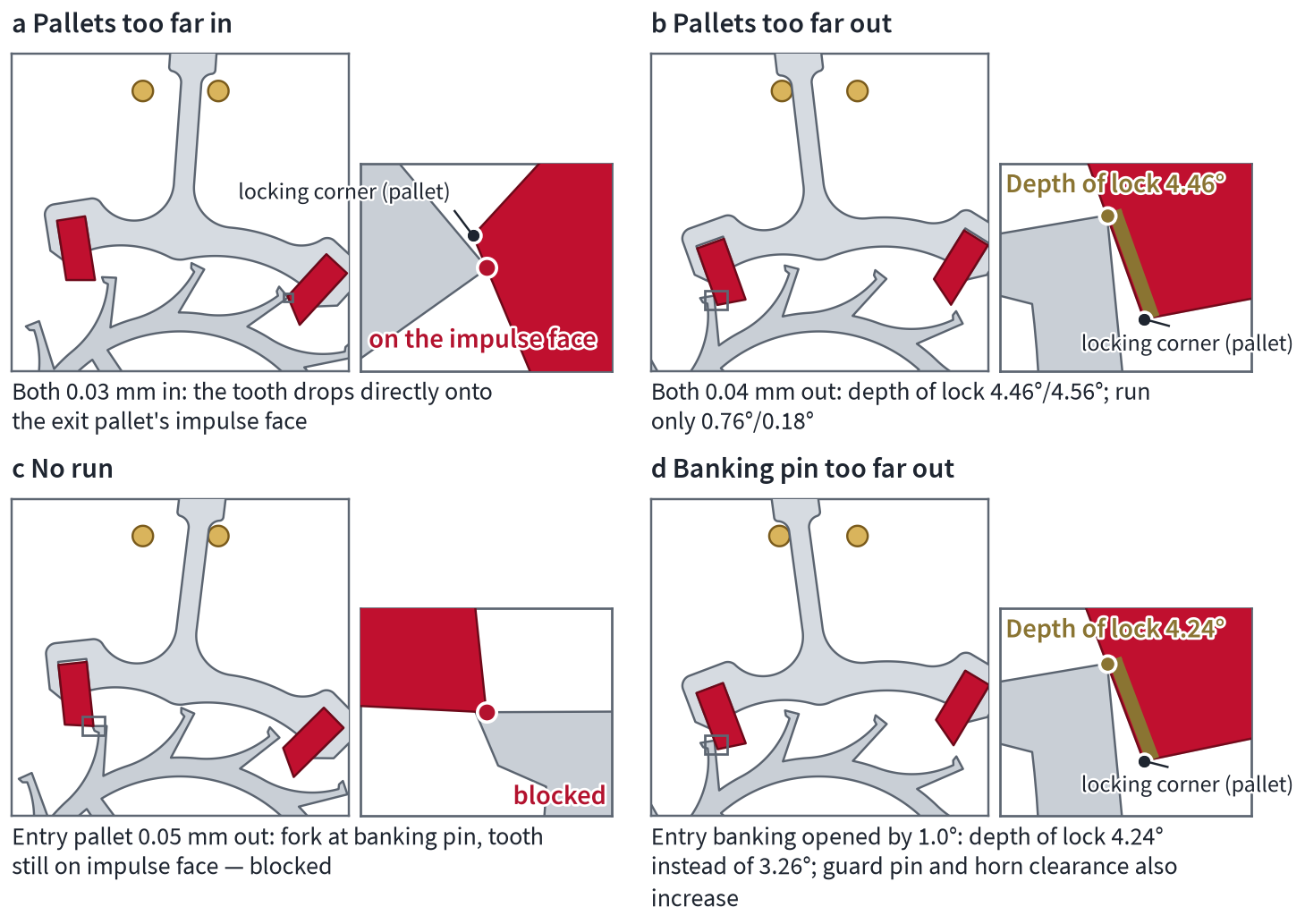
The four borderline cases at a glance: (a) pallets too far in, (b) pallets too far out, (c) no run to the banking, (d) banking pin too wide.
Adjusting the guard pin and horns
Almost all textbooks set the lock first and the guard pin only last (Two schools). When you move the pallet stones, the depth of lock changes but the guard pin clearance does not, and so the residual lock changes as well, that is, the lock that still remains with the guard pin in contact. If, on the other hand, you adjust the banking pins, depth of lock and guard pin clearance change by the same amount. Only when the pallet stones and banking pins are right do you therefore know how long the guard pin must be.
There are three cases with guard pin clearance. If it differs between the two sides, you adjust the guard pin or stone it on one side. If it is too large, you lengthen the guard pin by pushing it further through or stretching it. Bergeon offers a dedicated tool for this. After lengthening, check that the guard pin still passes freely through the passing hollow of the safety roller. If the guard pin clearance is too small and the guard pin rubs, shorten it on an oilstone across its axis, leaving a point of about 90°. Correct the guard pin clearance via the banking pins only according to the rule in the section Adjusting the banking, that is, only if the horn clearance and run to the banking on that side are also wrong.
How long the guard pin should be is given under Guard pin clearance. I set the guard pin clearance “nice and small, but distinct”. The guard pin must never rub, and it must hold the tooth on the locking face when you move the pallet fork back and forth. What matters is this tested function, not a figure from the textbook.
You change the horn clearance via the banking pins only if horn clearance, run to the banking and guard pin clearance on one side are all wrong together. Otherwise you work on the horns themselves: you polish them or carefully regrind them, and if the sides are unequal, you replace the impulse pin if necessary. You do not straighten the fork, because pallet forks of hardened steel break easily. Older textbooks straighten the fork at its root, and Bossart closes up a widened slot and then resets the horn clearance. I advise against both. If only the impulse pin is too small or worn, replace it with a suitable one. If, on the other hand, the slot is badly worn, the fork can hardly be repaired. In everyday repair work, you then usually replace the pallet fork. As a last resort, you fit a larger impulse pin and repolish the fork slot.
Finding | Cause | Remedy |
|---|---|---|
Guard pin clearance unequal | Guard pin crooked, point asymmetric | Adjust the guard pin or stone it on one side |
Guard pin clearance too large on both sides | Guard pin too short | push further through or stretch, then check the passing hollow |
Guard pin rubs on the roller | Guard pin too long | shorten on an oilstone across the axis, point about 90° |
Guard pin clearance, horn clearance and run to the banking too large on one side | Banking pin set too wide | Adjust the banking pin inwards |
Horn clearance locally too large or unequal | Horn shape, fork bent | Polish or regrind the horns; if the fork is bent, replace the pallet fork |
Fork clearance too large | Impulse pin too small or worn, slot widened | suitable impulse pin; if the fork is worn, usually a new pallet fork; as a last resort, a larger impulse pin and repolish the slot. Do not straighten the fork, it breaks easily. |
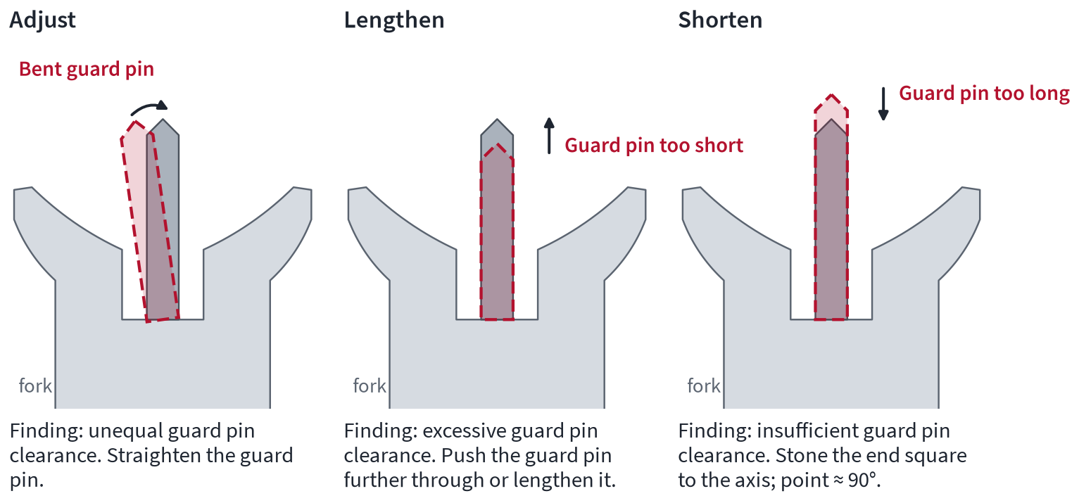
Three operations on the guard pin: adjusting, lengthening, shortening.
Workshop practice: shellac, heat, pallet-setting tool
When the shellac becomes warm, the pallet can be moved, and as soon as it cools, it holds the pallet firmly again. A pallet fork set in shellac withstands ordinary cleaning in watch-cleaning solution. Heated alcohol, on the other hand, dissolves shellac. This is used when a pallet is to be shellacked in completely anew (see below).
For moving the pallets, you use the pallet-setting tool (échappemètre), a small device that holds the pallet fork and adjusts the pallet finely. On the Bergeon tool, a spring lever clamps the pallet fork, a knurled screw sets the basic position of the pallet, and a dial gauge shows the travel in hundredths of a millimetre. The tool sits on a hot plate that either has a fixed temperature of 80 to 90 °C or can be regulated. I use an adjustable laboratory hot plate for this. However, the dial gauge shows only the travel of the pallet in its slot and not directly the change in lock, because the pallets sit at an angle in the pallet fork. This is why you work in small steps and check again in the movement after each step.
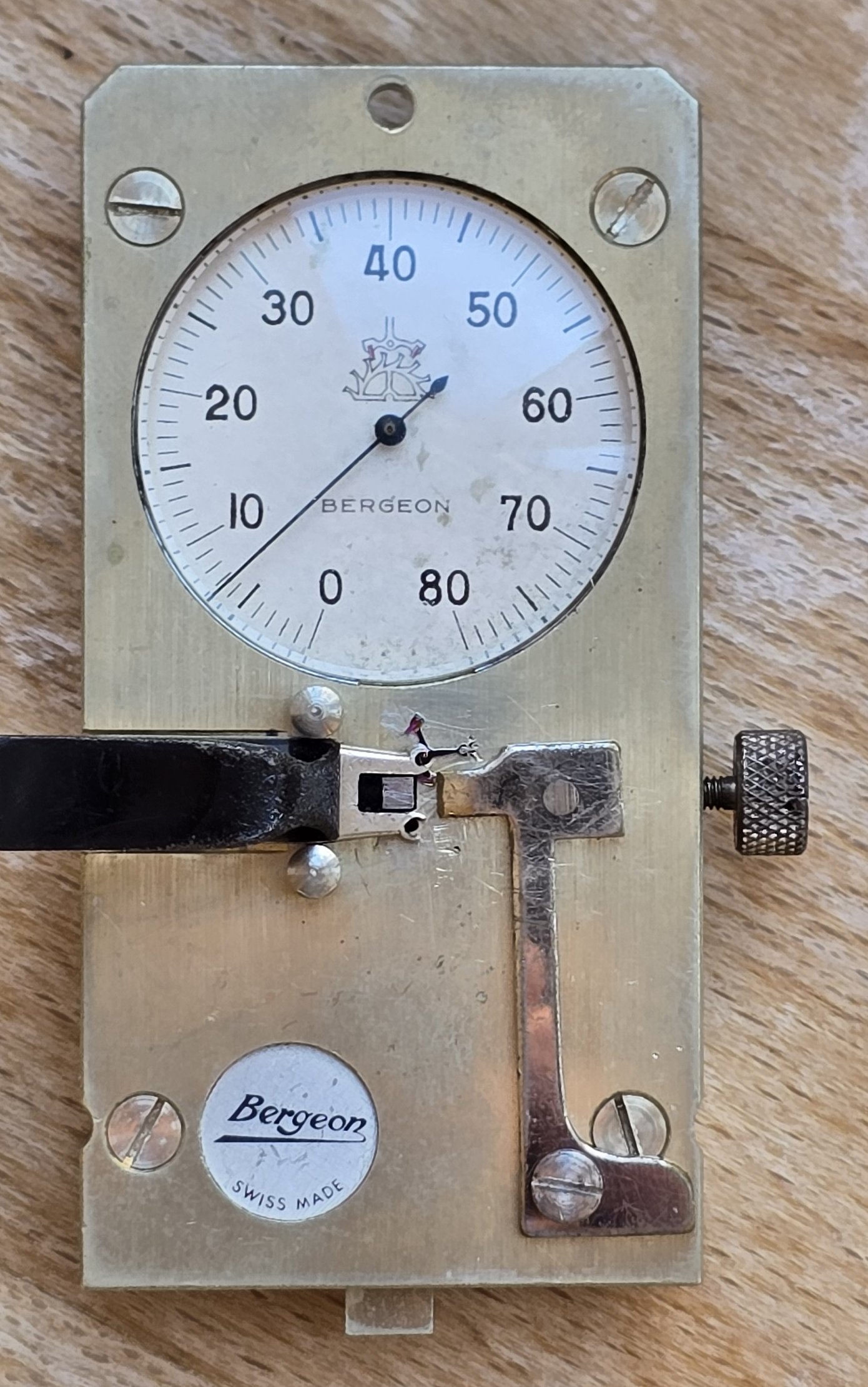
My Bergeon pallet-setting tool: on the left the spring lever that holds the pallet fork, on the right the knurled screw, above it the dial gauge.
The Pforzheim handout gives around 100 °C for the shellac. I set my laboratory hot plate to 120 to 160 °C, depending on how fluid the shellac is to become. Because shellac is a natural product, its melting behaviour also depends on its origin. Stand the warm tool on a wooden board or a tile, not on the cold bench. On the pallet warmer, when no pallet-setting tool is to hand, you push the pallet in with soft brass tweezers that lie flat against the whole impulse face, because steel tweezers will chip the stone. In the pallet-setting tool, you place a screwdriver behind the feeler lever of the measuring plate and use wedge or lever action for delicate adjustment. You push the pallet out from behind with a small oiler. You can see whether the pallet is moving from the gap at the back of the slot and, in the pallet-setting tool, on the scale.
If a pallet is to be shellacked in completely anew, all the old shellac must come out. Traditionally, the pallet fork is boiled out in methylated spirit over an open flame for this. By today's occupational safety standards, that is rather reckless, because methylated spirit catches fire easily. For boiling out, you therefore use at least a laboratory hot plate without an open flame, wear safety glasses and keep a fire blanket to hand.
Newer pallet forks, for example from ETA, have their pallets fitted with a synthetic adhesive instead of shellac. It too softens under heat, and the pallet can be moved. For a complete re-shellacking, however, it can only be removed reasonably well by mechanical means and with solvent.
But take care: burnt shellac turns cloudy and dark instead of clear, and its mechanical properties change.
For fresh setting in shellac, it is best to use a pallet warmer on the hot plate: a solid little brass pan with a hole for the pallet staff, which holds the temperature. The shellac pattern, that is, how the shellac lies around the pallet, is judged by cleanliness, location and quantity. With a good shellac pattern, the shellac fills the gap all round and lies on the pallet arm as a round, clear spot without bubbles, without running over the edges. It bridges the stone but does not form a drop that touches the mainplate or reduces the endshake. The pallet sits flat and flush. Then check that it is firm, for example by pressing on it with the oiler. Never swap the entry and exit pallets, because they have different dimensions and angles. In our model, they already differ in the length of the impulse face (0.434 and 0.468 mm).
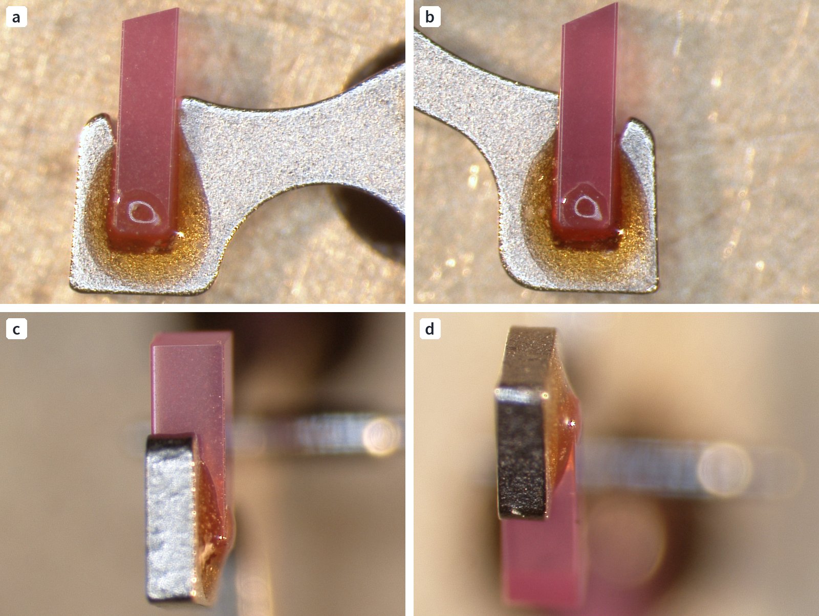
Pallets freshly set in shellac from my 2011 examination piece, under the microscope. At the top, in plan view, the shellac fills the gap and lies on the pallet arm as a round, clear spot. At the bottom, in side view, the pallets stand straight in the slot.
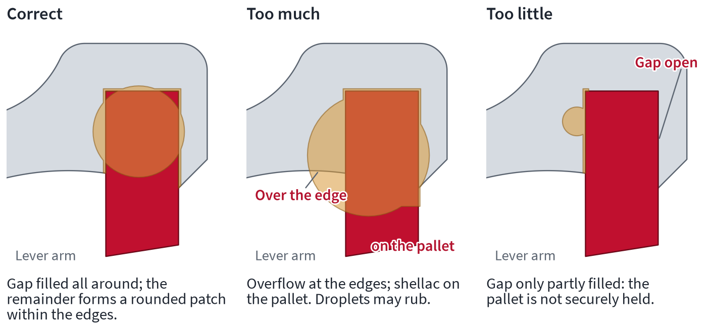
Shellac pattern good, too much, too little.
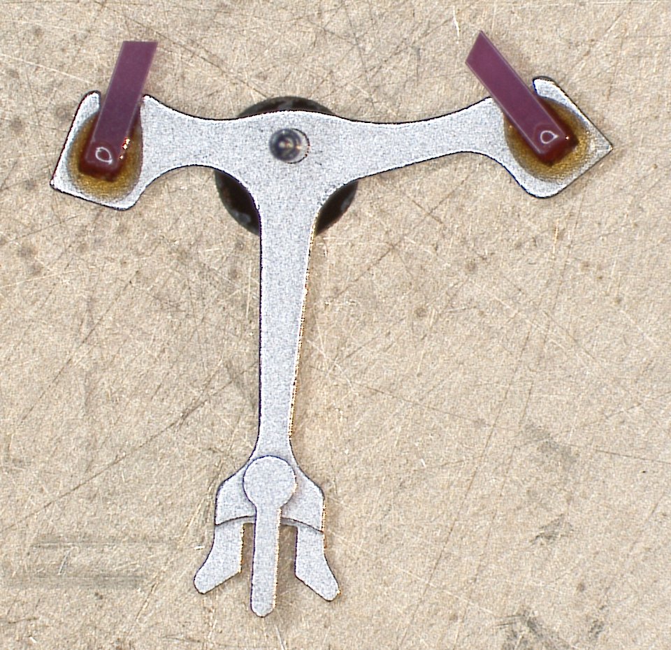
Pallet fork with pallets freshly set in shellac, fork, horns and guard pin, from my 2011 training piece.
Industry sometimes takes other routes. According to a report in UhrenMagazin, A. Lange & Söhne adjusts the pallets to within a few thousandths of a millimetre by warming the shellac. At Frédérique Constant, according to a report in the same magazine, the pallet fork and pallets are made from a single piece of silicon and cannot be moved. Instead, there are three pallet fork variants whose pallet spacing differs by 3 µm from one to the next. You first fit the standard version and then choose the appropriate variant.
During my internship in Glashütte in 2013, I got to know a pallet-moving device from the prototype department there. It moves the pallet via an eccentric and warms the shellac with hot air at 110 °C through a bore. The drawback is that the warm air makes the image in the microscope shimmer.
Key point: After every pallet move, check all clearances again.
The exercise solved: which pallet, which direction, how much
Let us recall the finding on the model before adjustment (entry/exit): depth of lock 2.98°/2.34°, drop lock 1.76°/2.00°, run to the banking 1.22°/0.34°, guard pin clearance 2.57°/2.07°. As a fraction of the impulse face, the drop lock is just over an eighth (0.14) on both sides. The depth of lock is just under a quarter (0.23) on entry, but only a sixth (0.17) on exit. If the guard pin were resting against the safety roller, only 0.27° of residual lock would remain on exit.
Now the two questions from the core rule help. Measured against the impulse face, the drop lock is the same on both sides, so the pallets match each other. Only depth of lock and run to the banking are unequal, so this is a position error, not a shape error. Only two interventions increase the run to the banking on exit: you push the entry pallet in (opposite side) or open the banking pin on exit (own side). The exit pallet does not help here, because it changes only the run to the banking on entry.
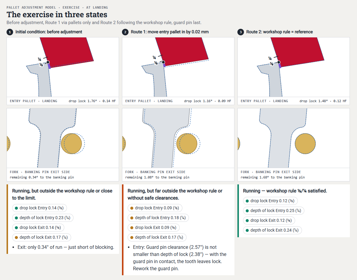 Open animation in a separate window
The exercise in three states: before adjustment, Route 1 with the warning “guard pin clearance greater than lock”, Route 2 following the workshop rule with the guard pin last.
Route 1, the pallets only. This is the stopgap when the banking is fixed. We push the entry pallet in by 0.02 mm. After that, the depth of lock is 2.38°/2.34°, the drop lock 1.16°/1.26° and the run to the banking 1.22°/1.08°, so the escapement is almost symmetrical. The series of measurements on the model shows how far you have to push. Even 0.005 mm gives 0.18° more run to the banking on exit, 0.01 mm gives 0.36° and 0.02 mm 0.74°. That is a fairly even 0.36 to 0.37° per hundredth of a millimetre. The drawback is a shallower lock than with the workshop rule (drop lock 1.16°/1.26° instead of 1.48°/1.68°). In addition, the guard pin clearance has remained unchanged. At 2.57°, it is now greater on entry than the depth of lock of 2.38°. If the guard pin were resting against the safety roller, the tooth would already be on the impulse face. The guard pin must therefore be reworked without fail.
Cross-check with the banking pin. If the banking is adjustable, you open the banking pin on exit instead. According to the core rule, you have to open it by around 0.9° (1.22° − 0.34° = 0.88°). Depth of lock and run to the banking on exit increase by this amount, both sides then have 1.22° run to the banking, and the drop lock stays the same. Here too the guard pin clearance grows with them, and the residual lock on exit remains at a scant 0.27°. Recalculated on the model, a banking pin on exit opened by 0.8° gives a depth of lock of 3.12°, a run to the banking of 1.12° and a guard pin clearance of 2.85°. At 1.0°, the figures are 3.32°, 1.32° and 3.05° (previously 2.34°, 0.34° and 2.07°). The drop lock remains 1.76°/2.00° in both cases.
Route 2, the workshop rule. The aim is a drop lock of one eighth and a depth of lock of one quarter of the impulse face. In the workshop, I do not estimate this in degrees but as a fraction of the impulse face, because such small angles cannot be seen by eye. The solution follows from the core rule in three steps:
The drop lock depends only on the pallets. If you push both pallets in by 0.005 mm, it falls from 1.76°/2.00° to 1.48°/1.68°, and that is one eighth of the impulse face on both sides.
You set the depth of lock on each side to one quarter of the impulse face with the banking pin on that side; the drop lock does not change in the process. If you open the banking pin on entry by 0.45° and the one on exit by 1.20°, the depth of lock is 3.26°/3.36° and the run to the banking 1.78°/1.68°. Between the two banking pins, the pallet fork now turns through 13.6° instead of 12.0°.
The banking pins have increased depth of lock and guard pin clearance by the same amount. The guard pin clearance is now 3.01°/3.23°, and with the guard pin in contact only 0.25°/0.13° of residual lock would remain. This is why you set the guard pin last. If you advance it by 0.040 mm, 1.90°/2.12° of guard pin clearance remains. On entry, it is thus just above the run to the banking, on exit somewhat further above it, because the banking pins determine the difference between the two sides. The residual lock is then 1.36°/1.24°, around 0.4 of the depth of lock.
How far you can advance the guard pin is limited by the passing hollow of the safety roller, because the guard pin must pass freely through it during unlocking. In the model, only 0.013 mm of clearance initially remained in the passing hollow, and from as little as 0.012 mm of advance the guard pin would have rubbed. We therefore cut the passing hollow deeper, so that at least 0.019 mm of clearance now remains. In finished movements, the passing hollow is cut out more generously anyway. The original guard pin, not advanced, serves as our example of a guard pin that is too short.
In the end, the safety clearances stand in a clear order, from the smallest value to the largest: run to the banking 1.78°/1.68°, guard pin clearance 1.90°/2.12°, horn clearance in the check position 2.58°/2.79°, depth of lock 3.26°/3.36°. The fact that the textbooks rank horn and guard pin clearance differently, and that some require half the lock with the guard pin in contact, is discussed under The ladder of safety clearances. For me, the tested function decides, because hardly any rule of thumb applies universally. On the adjusted model, the guard pin holds the tooth securely on the locking face, and the horn catches the impulse pin so early that 0.68°/0.57° of residual lock still remains.
Lever degrees, entry/exit | before adjustment | Route 1: entry pallet 0.02 mm in | Route 2: workshop rule, guard pin last |
|---|---|---|---|
Drop lock | 1.76/2.00 | 1.16/1.26 | 1.48/1.68 |
Depth of lock | 2.98/2.34 | 2.38/2.34 | 3.26/3.36 |
run to the banking | 1.22/0.34 | 1.22/1.08 | 1.78/1.68 |
Guard pin clearance | 2.57/2.07 | 2.57/2.07 (guard pin not yet readjusted) | 1.90/2.12 |
Residual lock with guard pin in contact | 0.41/0.27 | none/0.27 | 1.36/1.24 |
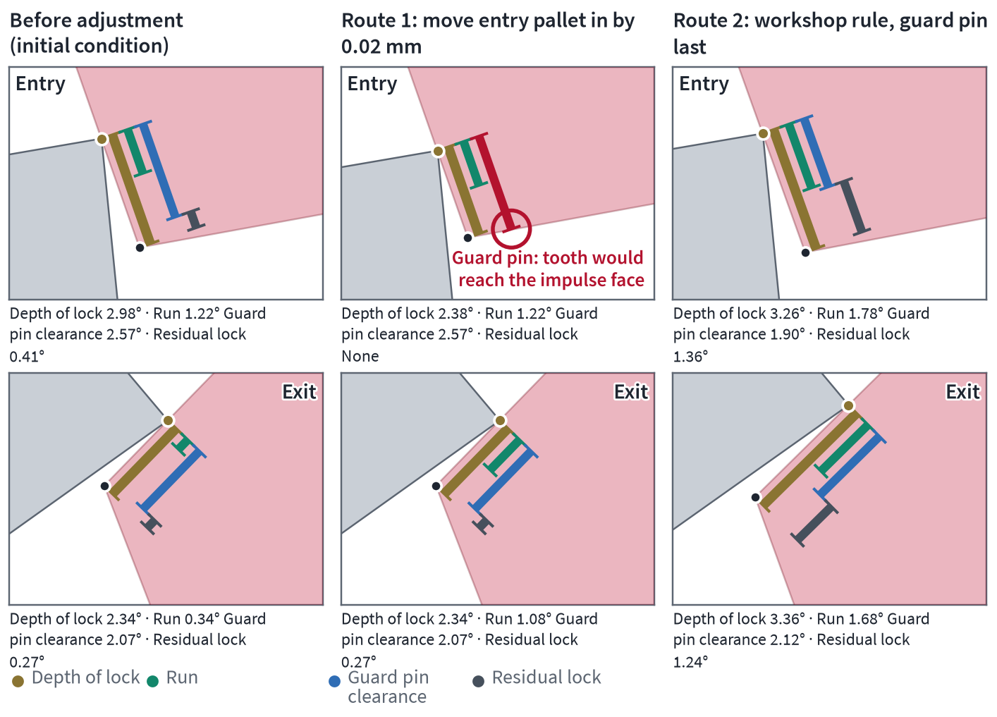
Before and after: before adjustment, Route 1, and Route 2 following the workshop rule with the guard pin last. In Route 1, the guard pin is marked red because the guard pin clearance is greater than the depth of lock.
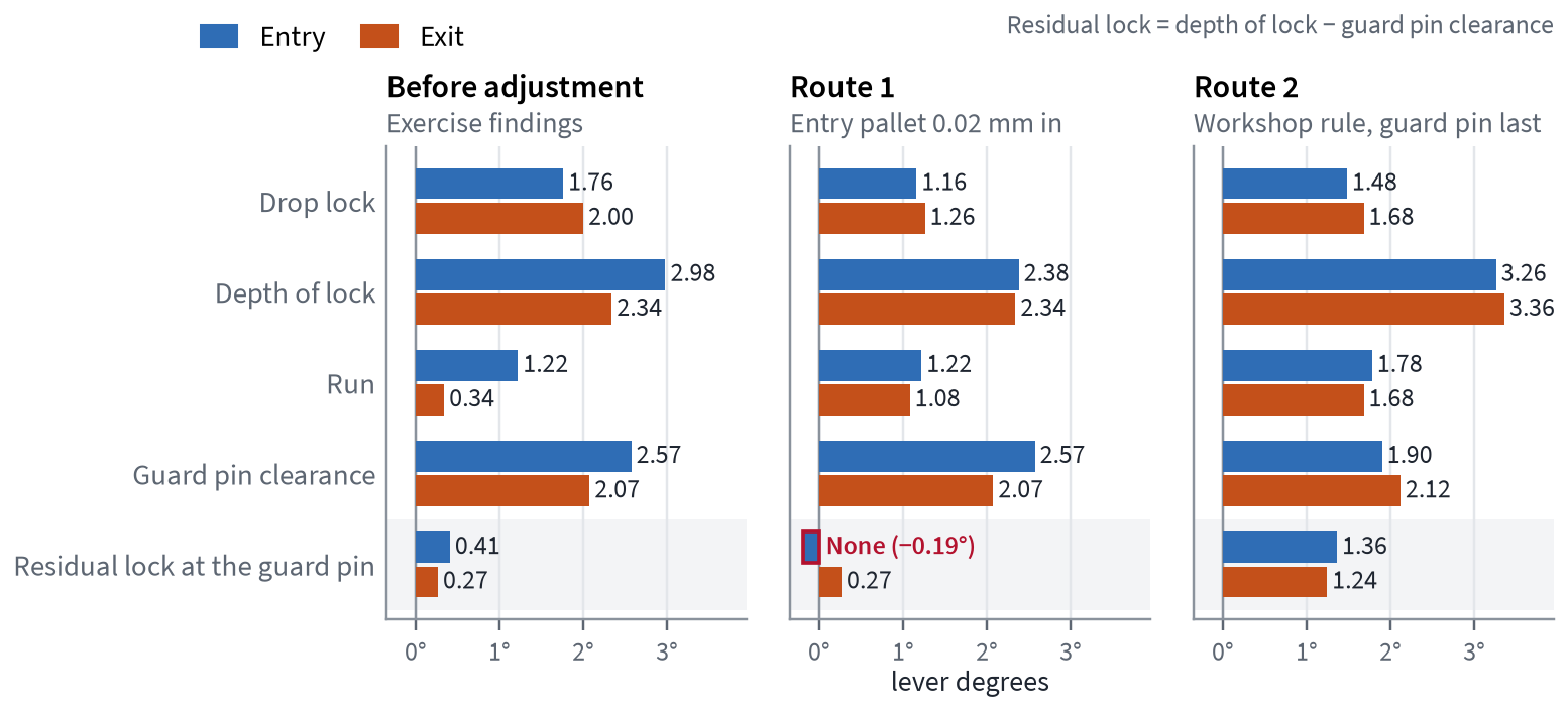
The three states of the exercise as bars, entry and exit each as a pair.
With fixed banking, as integrated into the pallet bridge in many modern wristwatches, only the pallets remain, and the result is sometimes a compromise. With adjustable banking, the workshop rule can be set exactly. In every case, after each change to the lock, check the guard pin and horn clearance again and set the guard pin clearance last.
In practice, on modern movements you will rarely find it necessary to adjust the length of the guard pin; it is usually perfect. So before you set to work on it, you should double-check that everything is in order with the lever banking.
Key point: The run to the banking on one side is changed by the pallet on the opposite side or by the banking pin on its own side. Afterwards, always check the guard pin.
Escapement faults: from symptom to cause
A watch does not arrive on the bench with the finding “too little lock”, but with a symptom: it stops on the wrist, knocks or has too little amplitude. This is why this chapter is arranged by symptom. Each profile states how you recognise the fault (eye, ear, timing machine), where it comes from, which check finds it and how to remedy it.
If you start from the component, look in the fault table in the appendix (Guide values and fault table) or in the Fault atlas. The simulator calculates position errors such as displaced pallets directly. Shape errors such as a fork that is too short are shown in the images, marked in red over the unaltered shape of our model.
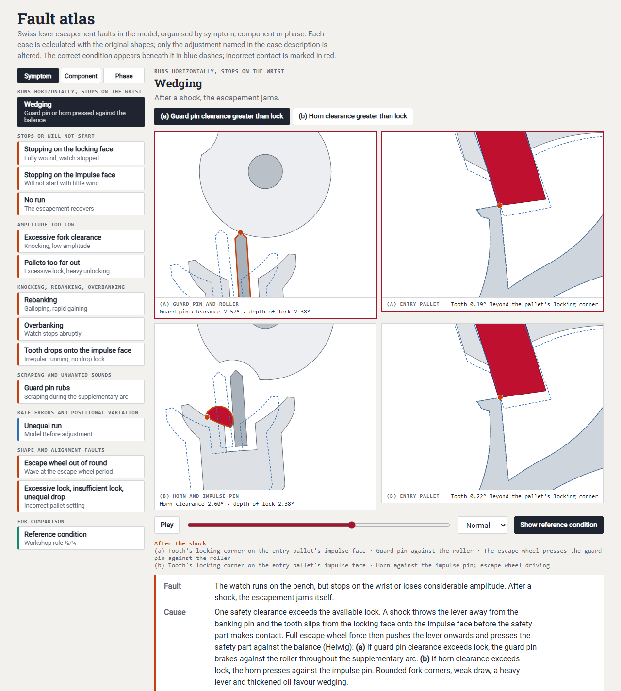 Open animation in a separate window
The fault atlas, switchable by symptom, component or phase.
Runs lying flat, stops on the wrist: wedging
On the bench the watch runs; on the wrist it stops or loses a great deal of amplitude. Behind this there is usually wedging: an escapement that gets itself stuck after a shock.
A shock throws the pallet fork away from the banking pin. During the supplementary arc the guard pin catches it at the safety roller, and if the impulse pin happens to be at the fork, the horn catches it. But if the guard pin clearance or the horn clearance is greater than the depth of lock, the tooth slips from the locking face onto the impulse face before that happens. The escape-wheel tooth then presses against the impulse face with full force and pushes the pallet fork further, so that the guard pin or horn presses against the balance (Helwig).
Two cases must be distinguished. If the guard pin clearance is too large, the guard pin presses against the safety roller and brakes the balance throughout the supplementary arc. If the horn clearance is too large, the horn presses against the impulse pin. Jendritzki cites as a typical case a guard pin that is too short combined with too little lock. Rounded fork corners, weak draw, a heavy pallet fork and thickened oil favour wedging.
Our model shows how tight this can get. Before adjustment, with the guard pin in contact, only 0.27° of residual lock remained on the exit side (guard pin clearance 2.07° with a depth of lock of 2.34°). After route 1 of the exercise, that is, with the entry pallet moved 0.02 mm in and no rework on the guard pin, the guard pin clearance on the entry side, at 2.57°, is even greater than the depth of lock of 2.38°. A shock that throws the pallet fork far enough for the guard pin to touch the safety roller then brings the tooth onto the impulse face. In the adjusted model, 1.36°/1.24° of residual lock remains with the guard pin in contact, around 0.4 of the depth of lock, and the horn clearance, at 2.58°/2.79° in the test position, is also clearly below the depth of lock of 3.26°/3.36°.
This is why I set the guard pin clearance “nice and small, but distinct”. It must be small enough that the tooth cannot leave the locking face when you move the pallet fork back and forth, and distinct enough that the guard pin never rubs. How to check the clearances is described under Horn clearance and Guard pin clearance. The section Adjusting the guard pin and horns describes how to adjust them.
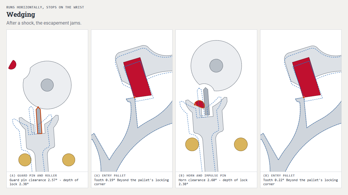 Open animation in a separate window
Wedging: (a) guard pin against the safety roller, (b) horn against the impulse pin, in each case with the tooth on the impulse face.
Stopping on the locking face or the impulse face
If the watch has stopped, the position of the tooth shows where to look. If it is on the locking face, the torque of the balance spring is not enough to unlock the pallet fork. If it is on the impulse face, the torque from the drive and the torque of the balance spring balance each other before impulse is complete.
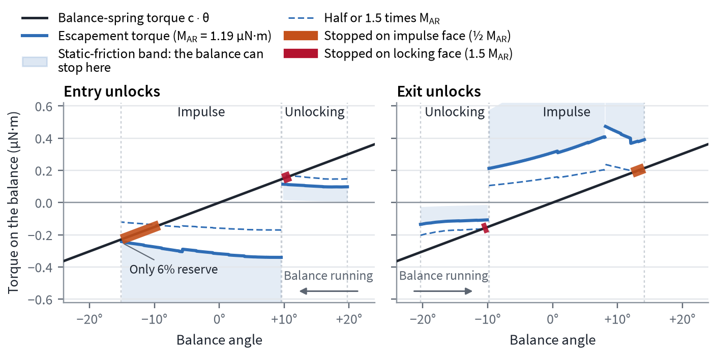
Balance spring torque against the escapement's torque on the balance. Where the two balance each other, the balance can stop. The torques are assumed.
Stopping on the locking face is the more dangerous case. The mainspring is well wound, and yet the watch has stopped. Winding further makes it worse, because the tooth then presses even harder on the locking face. Only moving the watch sets it going again (Bossart). Causes are too deep a lock, too large a draw angle, too small a lift angle (large roller, short fork), rough locking faces and gummed-up oil. In the workshop, the pallets are set shallower. In design, the pallet's impulse face is made steeper instead of shortening the pallet (So that the watch does not stop).
Every watch whose mainspring has run down stops on the impulse face, and usually a little winding is enough to set it going again. It is only a fault if it needs noticeably more winding than usual to do so (Function tests). Causes are too little force from the going train, rough impulse faces, too much, missing or gummed-up oil, an impulse pin that is not free in the fork slot, too large a lift angle (small roller, long fork) and incorrect beat (Bossart).
Good to know: if the pallet fork is already resting against the banking pin while the tooth is still on the impulse face, there is no run to the banking. The escapement “locks up”. That is an adjustment fault and not a force problem (Borderline cases: when the tooth drops onto the impulse face).
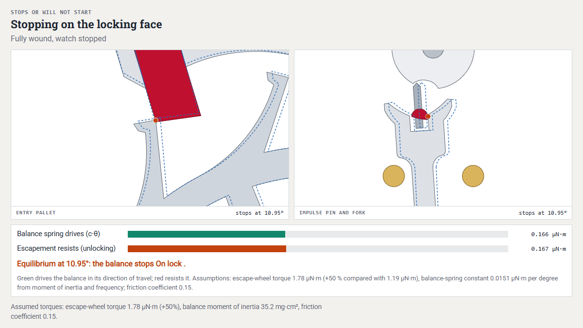 Open animation in a separate window
Stopping on the locking face, with an assumed torque at the escape wheel 50% above the normal value.
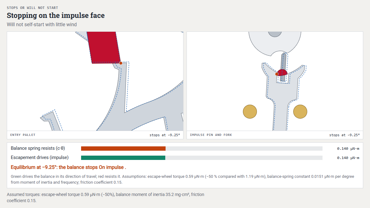 Open animation in a separate window
Stopping on the impulse face with a weak mainspring, with an assumed torque at the escape wheel 50% below the normal value.
The amplitude is too low: where the energy goes
Low amplitude is a common symptom, and the escapement is only one of its causes. In modern movements, Heffels almost always finds worn pivots and almost never damaged pallets or dented escape-wheel teeth. I would not entirely agree with this: wear tracks on the pallets' impulse faces are found in various forms on vintage watches, either as a track across the whole face or as a dug-out hollow roughly in the middle of the impulse face, where the moment of impulse transfer from the pallet fork to the balance takes place. Where there are such wear tracks on the pallet, the escape wheel is usually affected in some way as well.
Outside the escapement, the mesh between the barrel and the centre pinion transmits the greatest torque, so a fault in this mesh costs a lot of amplitude (Kilian Eisenegger's “Uhrenkonstruktion”). In the same book, the same going train with thinner pivots reaches an efficiency of 0.76 instead of 0.69, so around 10% more energy arrives at the escape wheel. In the vertical positions, pivot friction is about three times as great, and according to Berner the amplitude there is 40 to 60° lower. On top of this come magnetism and a pallet fork that sticks to dirty banking pins.
In the escapement, everything that goes beyond what is necessary costs energy: too deep a lock, too large a run to the banking, too much fork clearance, too large a drop and too strong a draw. Röseler put figures on this for a series-production movement. A shorter run to the banking or smaller fork clearance each yield around 7° of amplitude in the calculation; on the finished movement, the two together yielded 10 to 15°. What each of these adjustments costs in our model can be tried out in the Efficiency calculator. The figures are under Finally: what a good adjustment achieves.
Cause | Check | Remedy |
|---|---|---|
Lock too deep, run to the banking too large | Pallets shallower or banking pin closer | |
Fork clearance too large | usually a new pallet fork; if need be a larger impulse pin and re-polish the slot; do not adjust the fork | |
Drop too large, draw too strong | Replace pallets, pallet fork or escape wheel | |
Escapement dry or wrongly oiled | clean, re-lubricate | |
Rubbing due to endshake | correct heights | |
Pivots, bearings, barrel | repair pivots and bearings | |
Magnetism, sticking pallet fork | Check for magnetism, inspect banking pins | demagnetise, clean banking pins, never oil them |
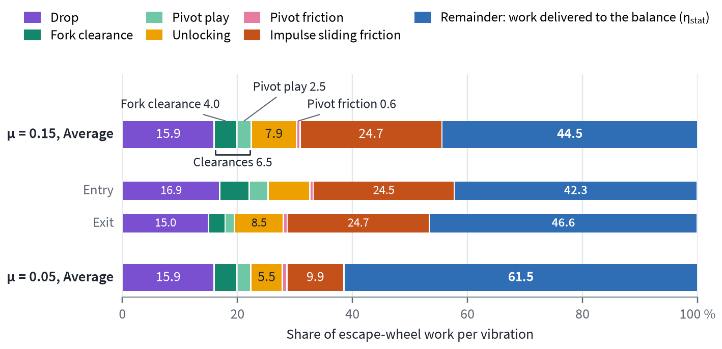
Where the energy delivered by the escape wheel goes in our model's escapement. The calculation is under Worked example B: where the two thirds go.
Knocking, rebanking, overbanking
If the watch knocks like a galloping horse and gains heavily, it is rebanking. The balance swings so far that at the end of the supplementary arc the impulse pin strikes the outside of a horn. Even slight rebanking changes the rate noticeably, and the timing machine shows jumps, up to a “snowstorm”. The amplitude at which rebanking begins is given under The ladder of safety clearances and the rebanking limit, and the Fault atlas shows the sequence.
Rebanking is checked in a vertical (hanging) position. Hold the watch firmly on the timing machine and wind it slowly by at least two turns of the crown. If the rate stays steady, all is well. If the watch briefly gains heavily, it is rebanking. Lying flat and fully wound, it must never rebank. Causes are too strong a mainspring, too strong a slipping spring, a damaged barrel and, according to Berner, click work with too little recoil, which overstrains the mainspring.
But take care: a lift angle entered too large mimics rebanking. With a movement whose lift angle is 44°, a timing machine set to 52° shows around 331° at an actual amplitude of 280° (Determining a movement's lift angle).
The sources disagree about the remedy. Exam answers for the final examination and the technical discussion in the master course start at the escapement and advise pulling both pallets out, because with deeper lock the balance must expend more energy at every unlocking, and the amplitude falls. Against this is the fact that more lock lowers efficiency, makes the watch lose in the vertical positions (Helwig) and departs from the ⅛/¼ workshop rule. Witschi starts at the cause and recommends replacing the mainspring, pallet fork or escape wheel. One manufacturer's workshop instructions start at the balance: a more viscous lubricant in the dial-side shock protection lowers the amplitude by 10 to 15°. If that is not enough, the barrel is replaced.
The problem is old. Since the 19th century there have been resilient bankings in many variants, intended to absorb the blow of rebanking. They did not catch on, because their advantages rarely justified the extra cost.
Overbanking, by contrast, is a failure of the safety features. During the supplementary arc the pallet fork jumps to the wrong side, on the way back the impulse pin strikes the outside of a horn instead of entering the slot, and the watch stops abruptly. Causes are a guard pin that is too short, bent or missing, too much endshake of the balance or pallet fork, an impulse pin that is too short, a shock, or hands turned backwards. When the hands are turned backwards, there is no driving force at the pallet fork. The Fault atlas shows the sequence with a guard pin that is too short, and the Test bench shows how to check guard pin clearance.
If, on the other hand, it already knocks during unlocking, the fork clearance is often too large: the impulse pin first travels through the free play and then strikes the flank of the slot (Fault atlas).
Scraping and other noises
Every extraneous noise that the timing machine shows is eliminated before the watch is handed back. I search in a fixed order, from coarse to fine:
By the time of lubrication at the latest, I have checked drop lock and depth of lock under the microscope.
Does the balance spring knock or rub anywhere: on the stud, the regulator pins, the balance cock or the balance rim?
Does the guard pin rub on the shock protection?
Does the impulse pin knock against the guard pin, or do the horns knock against the top of the double roller?
Only after that do a crooked guard pin or a crooked impulse pin come into question.
Finally, look for detail faults in the escapement itself.
Noise | Cause | Check |
|---|---|---|
Scraping throughout the supplementary arc | Guard pin rubs the safety roller, or the roller runs out of round | Guard pin clearance at three points |
Knocking at the dead point | Impulse pin knocks against the guard pin (height fault) | |
Rubbing as the impulse pin leaves the fork | Horn rubs the impulse pin | |
Catching at let-off | Let-off corner of the dropped tooth strikes the pallet's let-off corner (drop too small) | |
Rubbing in certain positions | Fork or horns on top of the double roller, guard pin on the shock protection, escape wheel on the pallet fork body |
The fault tables in Bossart and in the Theorie der Uhrmacherei also attribute a rubbing horn to banking that is too wide. In the model, however, horn clearance and run to the banking increase by the same amount when you open a banking pin. This point of contention is dealt with in the section Borderline cases: when the tooth drops onto the impulse face.
Too much oil can also make the balance spring stick, because the tooth spatters it off on impact (Jendritzki).
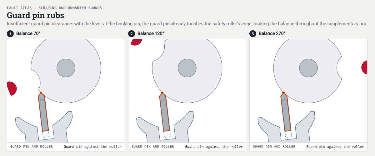 Open animation in a separate window
Guard pin clearance too small: the guard pin rubs throughout the supplementary arc and is free only in the passing hollow.
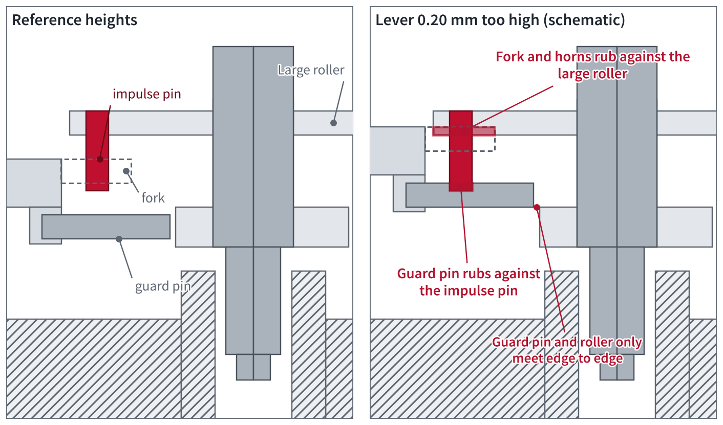
Too much endshake: where fork, horns and guard pin rub (schematic).
Rate errors and positional variation
An escapement can run reliably and still spoil the rate. Usually there is an inequality behind it, between entry and exit or between positions.
Unequal lock or unequal run to the banking comes from crooked banking pins or from a pallet fork that is not centred, that is, one where one pallet is set too deep and the other too shallow (Pforzheim question set). Reuer names the run to the banking, the pallet fork's centre of gravity, pivot shake and the condition of the fork slot as causes of position-dependent rate differences. A banking pin that is not upright gives the pallet fork more or less travel depending on the pallet fork's height, and the watch then runs differently dial up than dial down (Jendritzki).
A large poise error in the pallet fork can cancel the effect of draw in certain positions (Berner). A beat error that arises from unequal impulse cannot be corrected at the stud and changes with amplitude (Beat error without a timing machine, and function tests). If the run to the banking is too small, the timing machine's lines jump alternately to either side, and the sound of the pallet fork striking the banking pin is absent. If there is no run to the banking at all, the escapement locks up.
Our model before adjustment provides an example of such an inequality. On the entry side the run to the banking is 1.22°, on the exit side only 0.34°. This is the finding of the exercise, and the solution is under The exercise solved.
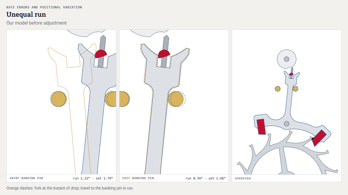 Open animation in a separate window
Our model before adjustment: run to the banking 1.22° on the entry side, 0.34° on the exit side.
Shape and position errors on the escape wheel, pallet fork, fork and pallets
Escape wheel. A pitch error makes the drop vary from tooth to tooth, and with an escape wheel that is out of round, as found above all in older watches, the depth of lock increases and decreases again over the course of one revolution. The timing machine then shows a wave in time with the escape wheel's rotation, every 6 seconds at 15 teeth and 18,000 vph (Escapement trace patterns). If our model's escape wheel sits 0.01 mm off centre, the teeth show 0.02 mm of runout on the dial gauge. Over one revolution the depth of lock then varies by ±0.3°, between 3.0° and 3.7° on the entry side and between 3.1° and 3.7° on the exit side, and the drop lock even by ±0.5°/±0.6°. A tooth that stands 0.01 mm further out therefore acts like a pallet set 0.01 mm deeper. A single tooth that is too long, by contrast, shows up only twice per revolution, once at each pallet, 1.0 s apart in the model. The remedy is to replace the escape wheel and then recheck lock and drop. But take care: similar fault patterns can also arise from a combination of toothing errors and bearing wear.
Pallets and pallet fork. The textbooks attribute unequal drop lock with equal run to the banking to the impulse-face angle and advise replacing the pallet. What our model shows on this is under One pallet or both? The decision path. Too large a drop comes from pallets that are too narrow, too small a drop from pallets that are too wide. If inside and outside drop are unequal, the pallet fork is too wide or too narrow, and a pallet staff that is too thick can also spread the pallet fork open (Bossart). After cleaning, check that the pallets are still firmly seated.
Fork, double roller and guard pin. A fork that is too long makes the impulse pin knock against the fork corners. A fork that is too short engages too shallowly and unlocks prematurely when jolted. According to Helwig, a bent fork is straightened at its root, not along its whole length. With pallet forks made of hardened steel you should not attempt this, however, because they break and cannot be bent. An upset double roller brings the guard pin and fork to the wrong height (Claußen). A bent guard pin makes the watch alternately run and stop; a broken one stops it.
If the safety roller's passing hollow is too shallow, the guard pin rubs in it, and the fault table of a master-course paper advises deepening it. That was exactly what was needed on our first sketched 3D model. Before adjustment, the guard pin could not be moved forward without rubbing in the passing hollow, and with the guard pin in contact only 0.25°/0.13° of lock remained. This is an example of a guard pin that is too short. Only with a more deeply cut passing hollow could the guard pin be moved forward by 0.040 mm. The figures are under Guard pin clearance.
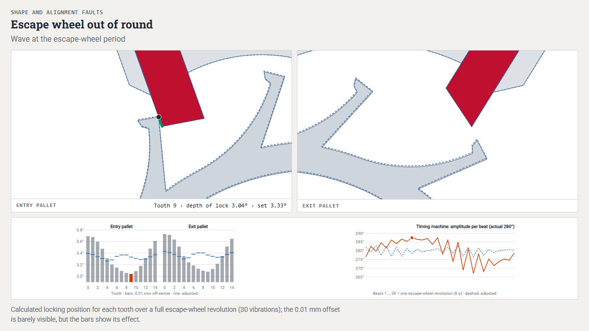 Open animation in a separate window
Escape wheel out of round.
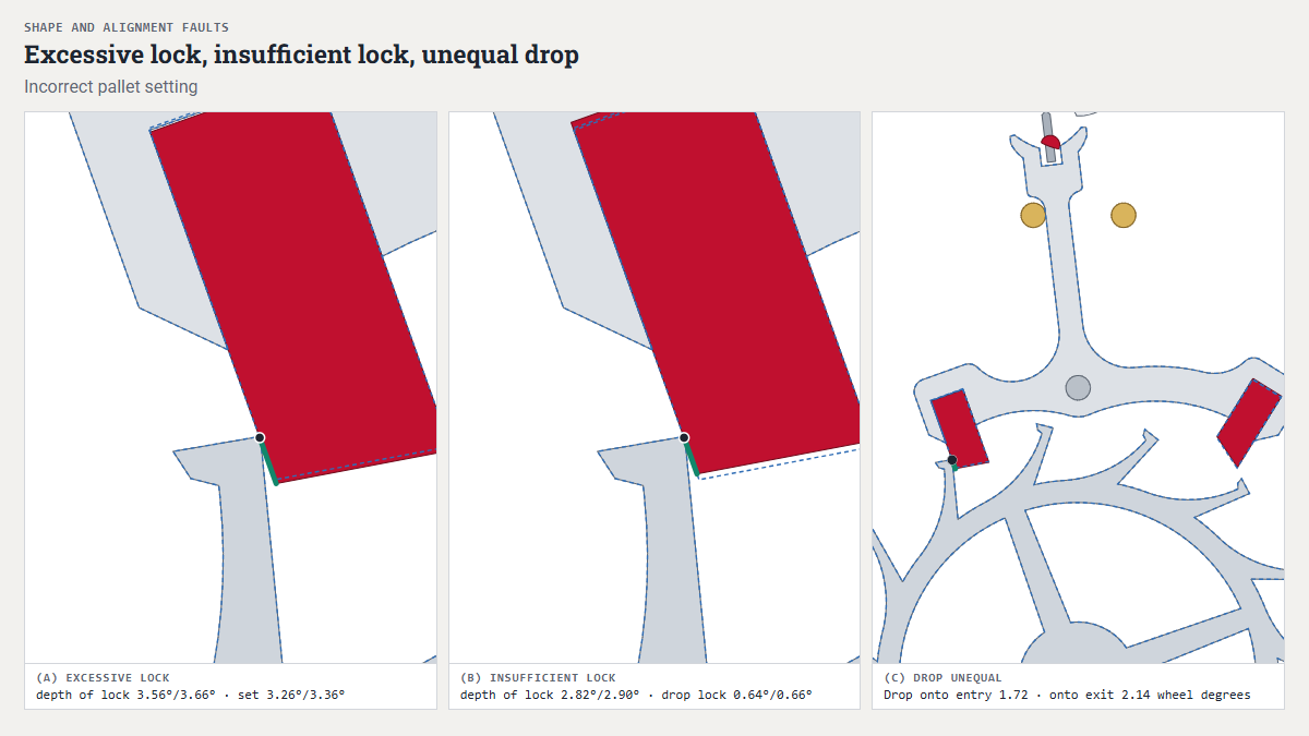 Open animation in a separate window
Lock too deep, too little lock, unequal drop.
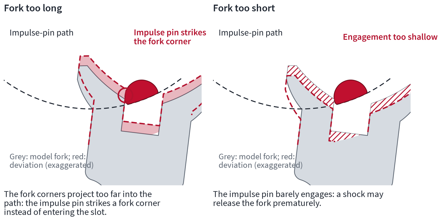
Fork too long and too short.
Not a fault: the delayed impulse
Impulse faces that are worn only in their second and third thirds, and two depressions in the fork slot, are not an escapement fault that we can correct. They arise because, in reality, the tooth flies freely for a short distance after unlocking and only meets the impulse face about ⅓ of the pallet width further along (Helwig, Röseler). The slow motion of the animations, by contrast, shows the tooth on the impulse face from the pallet's locking corner onwards. Nevertheless, worn pallets need to be replaced or, if the watchmaker has the skill, the impulse face must be reground and repolished.
This should not be confused with a tooth that lands directly on the impulse face during the drop (Borderline cases: when the tooth drops onto the impulse face). More on this under What really happens: the dynamics behind the slow motion.
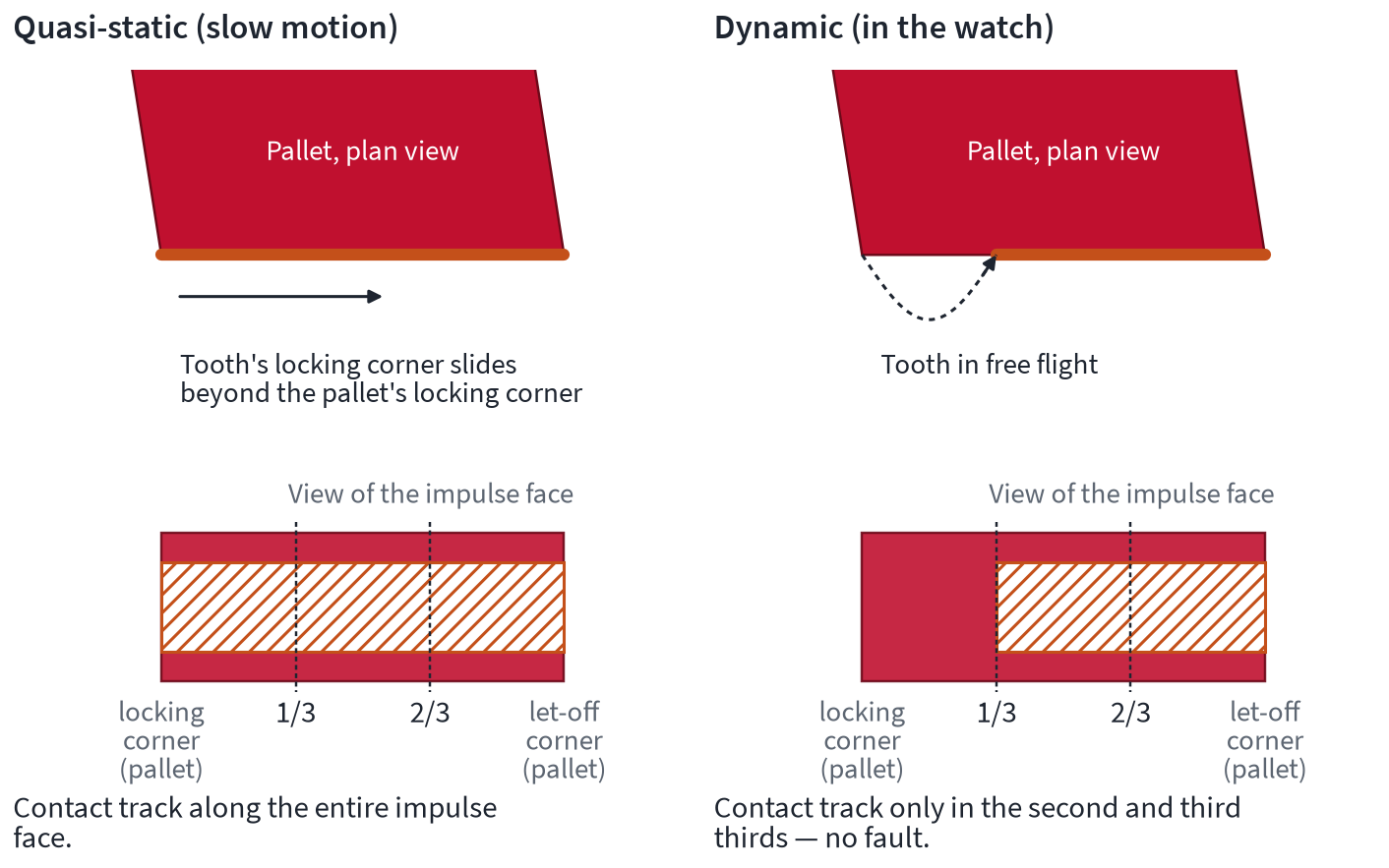
Schematic: wear track in slow motion and in some real examples.
Fault table by component
All faults are listed by component in the appendix under Guide values and fault table, covering the escape wheel and pallets, banking, fork and horns, guard pin and safety roller, and endshakes and oil. The Fault atlas can also be sorted by component.
Key point: If the watch runs lying flat but stops on the wrist, first check whether horn clearance and guard pin clearance are smaller than the depth of lock.
Lubrication and final check
Everything has been checked and adjusted. But how does the escapement stay in this condition? A drop of oil in the wrong place ruins the best adjustment, and a dry escapement gradually loses its good performance. The oils and greases available are described in the article Lubricants in watches.
When, where, and what never
Lubrication comes last, once all checks have been passed, the endshakes set and all components are clean. Oil belongs only on the tooth's sliding path, that is, on the locking and impulse faces of the pallets and on the faces of the club teeth that touch them.
The fork slot, impulse pin, horns, guard pin and banking pins are never oiled. Oil in these places attracts dirt and makes the lever arm stick to the banking pins.
To keep the oil on its path, the components are treated with epilame, that is, coated with an extremely thin film that prevents the oil from spreading. At ETA, according to the calibre sheet, the pallets and escape wheel are epilame-treated. If the movement then runs briefly without oil, the pallets scrape the film off at the points of contact, and the drop applied later stays there “as if in a playpen” (UhrenMagazin). How epilame works is explained in the article Epilames.
Whether the pallet staff pivots of pocket watches should be oiled is disputed. The training documents state clearly that they are not oiled, and the journeyman's examination even asks why the upper pivot in particular is left dry. Berner writes only that in small movements the pallet staff pivots can be left unoiled without disadvantage. The manufacturer's lubrication chart is binding, and you check it afresh for every calibre.
Key point: The need for oil depends on the pairing of materials, not on the escapement alone.
Two methods and the right amount
I learned to lubricate via the pallets, and that is also how many documents describe it. You assemble the movement up to the pallet bridge, without the balance, and wind the mainspring only minimally. A first, very small spot of oil goes in the middle of the impulse face of one pallet, smaller than the width of the tooth. Then you unlock the lever twice by guiding the lever arm with clean tweezers, but never at the point that strikes the banking pin, because no oil may get there. The next dose goes on the oil trail the tooth has drawn. 15 to 30 tiny doses are typical. I no longer work this way.
Today I oil via the teeth of the escape wheel, using a fine oiler to place a drop of exactly the right size on the front edge of each tooth. A variant from the literature first “inoculates” one tooth with a tiny amount, lets the escape wheel run for a few revolutions and applies further doses to the impulse faces of the teeth, each followed by a short run with minimal winding. Berner applies a very small drop to the pallet and, while the escape wheel is running, a second one.
For escape wheels with a Lubrifar coating, that is, a mixture of molybdenum disulphide and watch oil, ETA specifies two drops of Moebius 9415 on opposite teeth. Black traces on the pallets are normal here. The Boley catalogue lists Moebius 941 for pallet stones up to 21,600 vph and 9415 from 21,600 vph. During my time at Omega, we even went over to lubricating Lubrifar-coated escape wheels twice, 24 hours apart, because they do not always work reliably with the method described above. Lubrifar is now hardly used any more, because it leaves very unsightly “sludge” on the escape wheel, which is aesthetically impossible to explain in a luxury watch.
To check, I guide the balance with my thumb in a finger cot so that I can operate the lever by hand under the microscope. After the drop, I guide the tooth onto the impulse face and back a little. You then see the lubricating wedge, that is, the oil in the wedge-shaped gap between the impulse face of the pallet and the impulse face of the tooth. The apex of the wedge lies at the tooth's locking corner. From there, judged roughly by eye, the oil should fill at least a third of the wedge. With epilame I recommend a little more, because the escapement then holds more oil without it spreading.
The Pforzheim course notes give slightly different values: about 30% without epilame and up to 50% with epilame, less with a large wedge angle. According to the course notes, the wedge must still be at least 30% full after 24 hours.
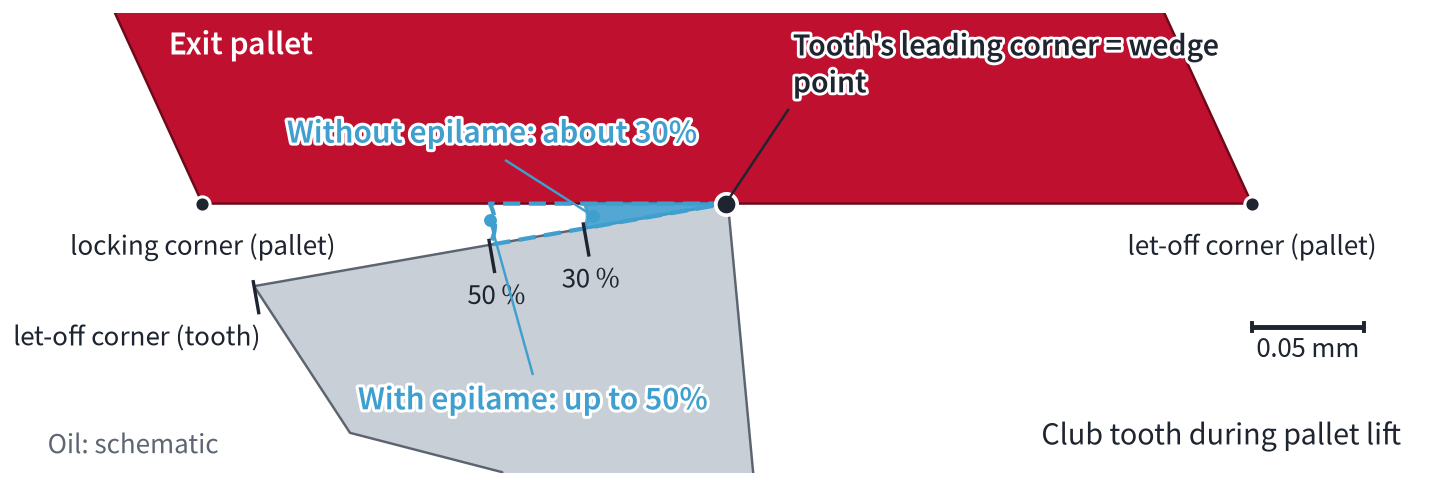
Lubricating wedge between the impulse faces of pallet and tooth, its apex at the tooth's locking corner. At least a third should be filled, a little more with epilame.
Symptom | Cause |
|---|---|
Oil track bulging or smeared | first drop too large or misplaced |
Oil on the flat face of the escape wheel | too much oil, movement allowed to run instead of unlocking the lever by hand, no epilame, residual dirt |
Oil on the top or underside of the pallet | too much oil, tooth not centred on the pallet (height error) |
Rate changes noticeably 6 to 24 months after the service | escapement dry, oil has run off, no reserve |
Final check on the timing machine
Finally, the watch is demagnetised and goes on the timing machine. It is measured in all positions, and after each change of position you wait until the balance has settled. Rate, amplitude and beat error are checked, plus the rebanking test when fully wound. Every extraneous noise is eliminated. The beat error must be below the manufacturer's limit, usually 0.6 to 0.8 ms. All limit values and the behaviour of amplitude and rate over the power reserve are shown in the section What the timing machine measures and which values apply; the guide values are also in the appendix under Guide values and fault table.
Heffels calls the timing machine a “multi-moment snapshot”, because it shows only the watch's condition during the measurement. That is why you measure again after 24 hours. The amplitude should then be at least 210° for manual winding and at least 190° for automatic winding (Theorie der Uhrmacherei). Isochronism is checked as the rate difference between 270° and 180° amplitude (WOSTEP Feinregulierung). All values go into the record.
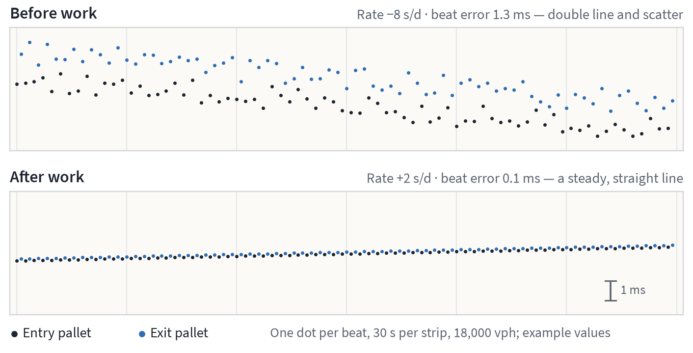
Schematic: timing machine traces before and after the work.
Part 2 at a glance and exam questions
Step | Target value | Our model |
|---|---|---|
per manufacturer's specification | – | |
smallest perceptible play | 0.48° | |
no tooth catches | – | |
drop lock ⅛ of the impulse face | 1.48°/1.68° | |
depth of lock ¼ of the impulse face | 3.26°/3.36°; 1.78°/1.68° | |
lever snaps back | – | |
smaller than the depth of lock | 2.58°/2.79° | |
tooth stays securely on the locking face | 1.90°/2.12° | |
per manufacturer, no stopping on the lock | – |
Check everything first, then change one thing, then check everything again.
Drop lock + run to the banking = depth of lock. According to the workshop rule, the drop lock is ⅛ and the depth of lock ¼ of the impulse face.
If you move a pallet stone, the drop lock changes on both sides and the depth of lock on its own side. If you adjust a banking pin, only the values on its own side change.
When the guard pin rests against the safety roller, the tooth must still lie securely on the locking face. The guard pin is adjusted last.
If the watch runs lying flat but stops on the wrist, first check whether horn clearance and guard pin clearance are smaller than the depth of lock.
1. What are drop lock, depth of lock and run to the banking?
The drop lock indicates how deep the tooth sits on the locking face when it drops, measured from the pallet's locking corner. The depth of lock is the full depth when the lever rests against the banking pin. The run to the banking is the distance through which the lever turns in between, from the drop to the banking pin. So: drop lock + run to the banking = depth of lock. According to the workshop rule, the drop lock is ⅛ and the depth of lock ¼ of the impulse face.
2. What is draw for, and how do you check it?
Draw holds the lever against the banking pin and brings it back after shocks. For the draw test, you lift the lever slightly away from the banking pin, within the lock, and release it. It must snap back immediately.
3. Fork clearance, horn clearance, guard pin clearance: which is which?
Fork clearance is the lateral play of the impulse pin in the fork slot. Horn clearance and guard pin clearance are the distance through which you can turn the lever from the banking pin until the horn touches the impulse pin or the guard pin touches the safety roller, respectively. Guard pin clearance is checked at three points at which the full edge of the safety roller faces the guard pin.
4. A pallet stone is pulled out. What changes?
The drop lock becomes larger on both sides, the depth of lock only on that pallet's side, and the run to the banking on the opposite side becomes smaller. Guard pin clearance stays the same. If you pull the exit pallet out by 0.01 mm on the model, the run to the banking on the entry side falls by 0.26°.
5. A banking pin is moved inwards. What stays the same?
The drop lock stays the same. The depth of lock, run to the banking, horn clearance and guard pin clearance on that side decrease by about the same amount. If no run to the banking is left, the escapement locks up.
6. How can you tell that a tooth drops onto the impulse face?
At the instant of drop, the tooth lands on the impulse face, beyond the pallet's locking corner, and the escape wheel pushes the lever across without the balance unlocking it. The timing machine's envelope trace then shows only two packets. This can usually be seen clearly only on pocket watches with a heavy balance, which then oscillates with an amplitude of only a few degrees. The remedy is to pull the pallet stones out.
7. On the exit side, the run to the banking is too small. Which pallet stone do you move, and in which direction?
You move the entry pallet in or open the banking pin on the exit side, because the run to the banking on one side is changed by the pallet on the opposite side and by the banking pin on its own side. Afterwards, always check the guard pin clearance.
8. Why is guard pin clearance adjusted last?
Only once the lock has been fully adjusted do you know how much guard pin clearance is permissible, because guard pin clearance must remain smaller than the lock. On the model, with the guard pin resting against the roller, only 0.25°/0.13° of lock remained at first, and 1.36°/1.24° after the guard pin had been moved forward.
9. How do you determine a movement's lift angle?
My 180° method is suitable for this. You wind the watch until a marked point on the balance rim flashes at the same place on the right and left swings. The balance is then oscillating at 180° amplitude. In this state, you change the lift angle setting on the timing machine until it also shows 180°. The value set is the movement's lift angle.
10. The watch runs lying flat and stops on the wrist. What do you check first?
First check whether horn clearance and guard pin clearance are smaller than the depth of lock. If either of these clearances is larger than the depth of lock, the tooth slips onto the impulse face in a shock, and the escapement becomes wedged.